After GSM call alarm and GSM SMS alarm as two independent modules, I introduce the Tiny GSM alarm system. The main characteristic of this new version is that this device can operate standalone or as a module for existing alarm system. In previous versions we had only the “enable” pin that armed/disarmed the system. Now, aside from that pin we can arm/disarm the system by calling it with our phone. Now, aside from that pin we can arm/disarm the system by calling it with our phone.
UPDATE 3 (2014-04-02): Source-code available on request, contact me on my e-mail.
UPDATE 2: New PCB with only DIP components (no SMD) is added to the archive for download. Thanks [eDo] for designing this PCB.
UPDATE 1: Since many people have trouble finding the PIC16F84A, I re-compiled the code to work with PIC16F628(A). It should work but I have not tested it yet on this uC so let me know if you have any problems with it!
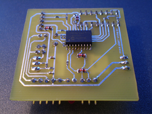
I used a very popular microcontroller from Microchip: PIC16F84A. This time I didn’t bother with external EEPROM memory for SMS storage because I used phone’s SIM SMS storage and phonebook memory.
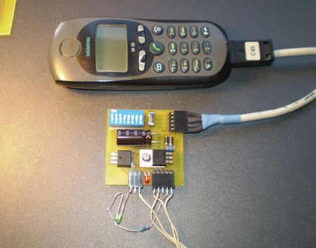
GSM phone that I used for development of this device is Siemens M35i (19200bps 8-N-1). It must work with other Siemens phones such as: S25, C35(i) (tested and works), A65 and so on (X35, X45)… It is very recommended to modify the phone so that it can be powered and turned on by the device. Also, the SIM PIN code request should be disabled!
Operation
After powering up the device, LED will blink once after it reads some settings from EEPROM. Now, after 2 seconds it will turn on the phone with a 2 second-impulse and pause for 6 seconds to allow phone to turn on. After that, initialization follows with the AT commands stored in EEPROM. They are in EEPROM only to save FLASH memory because this PIC has only 1 kb of FLASH for program. If during the serial communication between the PIC and the GSM some data is lost or never received (3 seconds timeout), the GSM phone will be reinitialized. After the fourth failure, PIC will execute that 2 seconds impulse that will turn the phone on because it thinks it has turned itself off. Also, PIC will do a 5 minute gsm-alive check and turn it on if it doesn’t receive data. During those 5 minutes if alarm condition occurs, the PIC will turn the phone on immediately and report the alarm.
Arming and disarming the system
System can be armed and disarmed by calling it from the other phone (who’s number is stored in system’s gsm’s phonebook of course) if it is configured properly with option opt 3, and/or by using the hardware “enable” pin (it is possible to use both at the same time but it might get confusing). If only arming/disarming by call is used, than the “enable” pin must be connected to ground at all times. This can be done with switch who’s options is opt 7. In case where calling arm/disarm is not used, than options opt 4 and 5 have other meaning: delayed armed state entering and delayed alarm condition, respectively.
When system is being armed/disarmed with calling function there are two methods of reporting that action: siren beeping (chirping), just like in car-alarms or by callback function. Callback function is activated only when system is disarmed. It will call back the user who have just disarmed the system to let him know what happened. This is helpful when you call your alarm by accident and disarm it! The system can only be disarmed either by the first number in SIM phonebook memory or any stored number. That choice is configured with option opt 4. Note: this option does not effect the number of alarm condition recipients.
Alarm condition
The system goes to “alarm state” when it’s armed and when the sensor input is triggered. It activates the siren output for 45 seconds and starts the GSM alerting procedure by calling or sending the SMS. Alerting procedure (SMS or by call) will be issued to either all numbers/sms recipients or to just first position (phonebook or SMS index location) which is configurable with option opt 2. Alerting by call can be executed to just first number or all numbers in this fashion: Numbers (or just the first one) are called in circular fashion until the call is established to any of recipients. After successful call establishment the calling procedure is completed. If an alarm condition occurs in next 25 seconds after alerting is completed, another alerting procedure will not take place. If an error occurs during calling, there is an 8 seconds pause not to overload the phone. Alerting with SMS messages can also be done by sending just first message or all of them, and it works in this fashion: All SMS messages will be sent (or just the first one), which means that all users will be alerted by this method, not like with the calling procedure where only first one that accepts the call is notified.
Status LED
There is a status LED on this device that can be helpful. When system is armed this LED blinks in 1.8 second interval. When disarmed, the LED is turned off. Right after disarming the system this LED will report us of the conditions that device was in during it’s last armed state, by blinking:
1. 5 blinks = system was in alarm state, eg. alarm was triggered
2. 3 blinks = there was an error with PIC-GSM serial communication
3. 2 blinks = there was an error during alarm condition reporting via GSM – it would be wise to check the prepaid credit
4. 1 blink = there was an error during alarm reporting via call
This blinking will be done three times upon disarming and during that time it is not possible to re-arm the system.
About the phonebook entries and SMS messages on SIM card
Well, we all know how to put a number in phonebook. Even so, it is important to place numbers on a SIM card, not the phone’s memory! All phonebook entries must be in locations from 001, 002, 003,… to as many as you like. Don’t skip a location! The SMS messages are a bit different as there is no way you can determine what index message is on. So it is wise to delete all messages and create one by one. That way you will know that the first message created is in the first position. Also, if there are for example three messages on a SIM card, deleting the second will brake the queue and reporting will be done by sending only the first message! – This applies to phonebook entries as well.
Backup power
It is possible to connect a backup power source to the device. It can be a rechargeable battery or dry non-rechargeable battery pack. There is a jumper on board that enables and disables charging of the backup battery from the primary power source. Be sure to remove the jumper if dry non-rechargeable batteries are used!
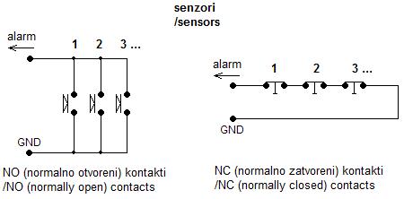
Sensors
The device supports using both types of sensors: with NO (more sensors connected in parallel) and NC (more sensors connected in serial fashion) contacts. The type of sensor used is configured with option opt 6.
Device possibilities and configuration options
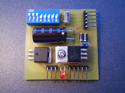
This device, as we already know by now, can report alarm condition by using SMS messages or placing a voice call to as many numbers as we like. Besides the remote alerting functionality it has an output MOSFET transistor that can be used to turn on the outside siren and strobe light when alarm activates.
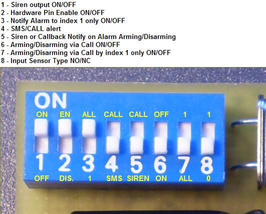
Setting up the device is accomplished by 8 DIP switches that are on board. We can setup the following options: (please note, option such as “opt 2” does not correspond to switch number 2, etc.)
– opt 1) Notification type: SMS or CALL (DIP switch no. 4)
– opt 2) Alarm notification to only index 1 in SIM phonebook or to all (DIP switch no. 3)
– opt 3) Arming/disarming by call-in enabled/disabled (DIP switch no. 6)
– opt 4) Arming/disarming only by entry at index 1 from SIM phonebook when option 3 is enabled. If option 3 is disabled, than this switch enables/disables the 8.5 seconds countdown timer that delays switching to “armed” state. (DIP switch no. 7)
– opt 5) Notification of arming/disarming the system by using siren chirp or callback functionality when option 3 is enabled. If option 3 is disabled than this switch is used for delayed alarm activation after 5 seconds. (DIP switch no. 5)
– opt 6) Type of sensor used: NO or NC. *Requires device reset to apply new setup. (DIP switch no. 8)
– opt 7) Connecting the hardware enable pin constantly to GND (constant hardware “arm”). (DIP switch no. 2)
– opt 8) Enable/disable siren output. (DIP switch no. 1)
GSM phone modification
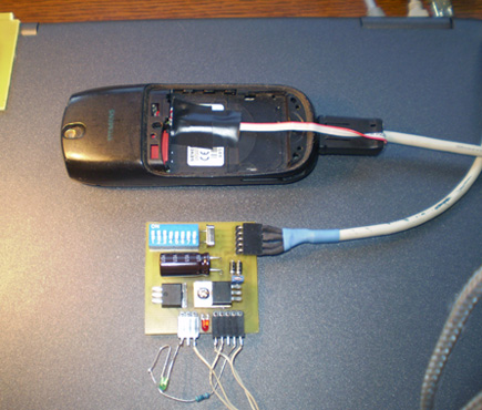
GSM phone is powered from a device itself through 3A LM350 or weaker LM150 voltage regulator. This means that two wires must be extracted from inside the phone: “BAT -” and “BAT +”. Some phones will not work like this, so you need to keep the battery connected, just remove battery cells and keep the electronics of the battery.
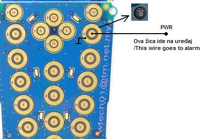
Aside from this, it is recommended to connect another wire that will be soldered to phone’s keypad like in the picture below. This will turn on the phone when it turns off.
Source : Tiny GSM alarm system using PIC16F84A
About The Author
Ibrar Ayyub
I am an experienced technical writer holding a Master's degree in computer science from BZU Multan, Pakistan University. With a background spanning various industries, particularly in home automation and engineering, I have honed my skills in crafting clear and concise content. Proficient in leveraging infographics and diagrams, I strive to simplify complex concepts for readers. My strength lies in thorough research and presenting information in a structured and logical format.
Follow Us:LinkedinTwitter