We created Skywriter because lightsabers are cool. Although we are fans, we are not passionate about the Star Wars franchise. However, we are passionate about the technology in Star Wars. For our final project, we wanted to replicate the futuristic lightsaber. And add a twist with persistence-of-vision. This project has been a great exercise in integrating peripherals, multi-threaded programming, and soldering. Lots and lots of soldering.
HIGH LEVELDESIGN
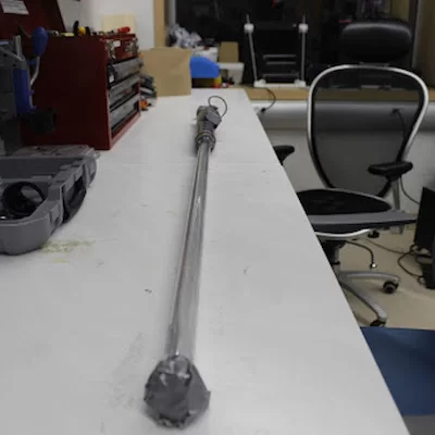
Skywriter was designed on the exterior to replicate the appearance of the lightsabers in Star Wars movies. As a result, we cut PVC piping for the handle to be about 1 foot in length. We use about 3 feet of clear polycarbonate tubing and LEDs for the blade of the lightsaber.
To generate the sounds from the blade, we included amplifier and speaker components. The amplifier is soldered onto a project board inside the handle. The speaker sits at the base of the handle. To generate sounds, we run an ISR on the microcontroller performing direct digital synthesis.
To control the LEDs, in particular to generate persistence of vision, we include a gyroscope in our handle that enables us to measure the angle of the lightsaber. The measured angle is input into a mapping function that maps each LED to a coordinate on the image to be drawn.
Lucasfilm owns rights to Star Wars and associated intellectual property like the lightsaber. We will be careful to not create any copyright issues by selling or claiming ideas like the lightsaber as our own. Lucasfilm historically is supportive of the fan community creating projects based on the films
Note: There is a similar project found here by bitluni. We referenced their documentation while purchasing parts. The circuit design, software and integration are developed independently.
HARDWARE DESIGN
BLADE
Tube: The blade of our system consists of an LED strip inside of a polycarbonate tube. To emulate the proportions of the movie, we chose to make our blade 3 feet long. We chose to purchase a 3 foot long clear polycarbonate with ¾” diameter on the outside bought here.
LEDs: Inside of the tube, we inserted the Adafruit Dotstar Digital LED strip. We chose the strip with 144 LEDs because it is closest in length to 3 feet. However, this strip is slightly longer than 3 feet. To deal with the excess, we roll the extra strip material into a tight ball and tape it at the top of the blade.
HANDLE
Pipe: The structure of our handle is a PVC pipe. The length of the handle is 1.5” PVC pipe purchased from home depot, cut to about 16 inches in length. The blade’s polycarbonate tube connects to the handle via a ¾”-1” PVC pipe adaptor. The adaptor is slightly too large and needs to be sanded. It is then pressure fit into the 1.5” PVC pipe. The polycarbonate tube is also pressure fit into the adaptor. Duct tape is used to increase friction and the tightness of the pressure fit.
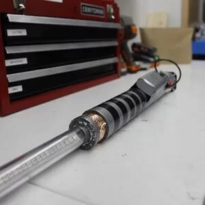
Tape: The handle is stylized with various types of tape. First, the entire handle was wrapped with grey duct tape, giving it its predominant silver color. Next, we add black grips with blakc electrical tape. Lastly, we use bronze copper tape to accent the adaptor.
INTERIOR CIRCUITS
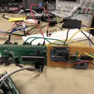
Within the handle is a microcontroller board and a solder board. These two boards are hot glued together. Microcontroller: Our project uses the PIC32MX microcontroller. The board design is provided through the ECE 4760 course, and is referred to as Sean Caroll’s Little board (SECALB).
Solder Board: Adjacent to the microcontroller board is a solder board with most of the system’s peripherals. See the appendix for a schematic of the system
Amplifier – to amplify the audio for our system, we use Adafruit’s 3.7W Class D Amplifier.
DAC – we use a digital to analog converter to convert the digital synthesis into analog values for the amplifier. We use the MCP4822.
MPU6050 – to measure the angle of the lightsaber, we use Adafruit’s Triple-Axis Accelerometer
- Level shifter – we use the DM74L1S to convert the 3V signal from the microcontroller to 5V signals needed to control the LEDs.
EXTERIOR COMPONENTS
Power: Our system has two portable charges, either of which can power the system. There is an internal power bank that we were given from a friend. It is a standard 5V 1A phone portable charger. The black cable is used to charge this internal powerbank. Next, there is also an external power supply. On the lightsaber, this looks like a lump on the hilt of the lightsaber. This is a larger 5V 2A portable charger. It is secured to the handle with duct tape. The white cable connects this portable charger to the system. Typically the internal power supply can only power the system for about a minute. The external power supply can power the system for over 30 minutes.
Speaker: The speaker is placed at the bottom of the lightsaber hilt. This allows the sound to emanate without obstruction. The handle’s interior also echoes sounds emanated from the speaker slightly. This creates a spooky effect. We chose to use a small 1 ohm speaker like the one found here. The speaker is fixed to the rear of the handle with duct tape.
Switches and buttons: There is a silver switch near the bottom of the lightsaber hilt. This switch toggles the power supply used to power the system. There is a red button opposite of the silver switch. This button toggles the state operating state of the lightsaber: off, normal, square, star wars, party. The switch and button are fixed with hot glue.
SOFTWARE DESIGN
The software design consists of three simple threads; ISR thread, I2C thread and the main control thread. The job of the ISR thread is to create a sine wave in an envelope to produce the sound for start up and the regular buzz noise that changes with movement. The I2C thread continuously scans for the values from the IMU unit and stores the values for the acceleration and gyroscope in the three axis and also computes the pitch. The last control thread is used to scan for the button press and toggle between modes and set the LED colours using SPI protocol as per the mode we are in.
ISR THREAD
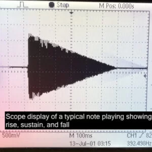
This part of the code runs at a frequency of 44 kHz and updates the DAC output as commanded by the user. Variables DDS_Phase and DDS_Increment are updated at every cycle of the ISR by looking up the sine table for the frequency specified by the user. In case of no sound both the variables are set to zero. However, use of this produces just a simple sine wave at a certain frequency and that can be used for the frequency test mode. The use of this uniform sine wave is not so pleasing to the ear and hence, we modulated the wave to produce a sound closer to that you hear from a light saber as in the movies. This can be done by sending the sine wave through an envelope with a very sharp sustain time, and a longer rise and delay time , and setting the frequency to 110 Hz. Also, a second frequency, which is two times the original, is embedded into the sine wave with the equation:
wave = envelopemain * sin(Fmain*t + envelopefm*(sin(Ffm*t)))
The variables FM_DDS_phase and FM_DDS_increment are also updated with each cycle for the FM synthesis.
I2C THREAD
The MPU-6050 devices combine a 3-axis gyroscope and a 3-axis accelerometer on the same silicon die. This device communicates the values using I2C protocol. We have used the ‘i2c_helper.h’ library written and used by students in previous projects over the last few years. We have set up the i2c protocol in the main function at a clock of 400 kHz and have called the i2c thread to continuously scan and read the values from the MPU6050 peripheral. These values are then stored in a global variable for the rest of the threads to use. We also calculated the value of pitch in this thread and saved it to a global variable. Pitch gives us the angle at which the set up is raised. In order to produce an image with persistence of vision it is essential to know the angle the light saber makes with the Z-axis. This pitch is calculated using the formula:

pitch = 180 * atan2(accelX, sqrt(accelY*accelY + accelZ*accelZ))/PI;
However, the accelerometer values produced by the MPU peripheral are known to be very dynamic and hence we implemented a digital low pass filter to couple it with the gyroscope values to use in the formula and came up with the following snippet of code:
accum_values[0] = accum_values[0]*0.75 + .25* values[0]/MAX_G_VALUE;
accum_values[1] = accum_values[1]*0.75 + .25* values[1]/MAX_G_VALUE;
accum_values[2] = accum_values[2]*0.75 + .25* values[2]/MAX_G_VALUE;
pitch = atan2((-accum_values[1]) , sqrt(accum_values[0] * accum_values[0] + accum_values[2] * accum_values[2]));//computes the pitch
SPI: LED
The Dot-star pixel strip we are using for the project communicates using the SPI protocol. The software for the same was already written by Prof Bruce Land and available on the course website which we implemented and changed it to our convenience. First we set up the SPI channel 2 for the LED strip with RB5 as the data out pin. The functions to write led onto the led strip take the HSV components for the light color and the index i (ranging from 0 to 143) for the position of the LED to light up. Although a similar function that takes RGB values is included in the code we have made use of HSV only.

CONTROL THREAD
The control thread runs in a loop with a time delay of 2 mS. The loop starts with checking for a button press on the pin A0. This button press toggles between the five modes we have; OFF, start up, Square, Star wars and party mode. Each of the modes has its own functioning and color configuration to light up the LED strip.
OFF mode: In this mode we simply set h,s,v to zero so the light saber isn’t turned on.
Start up mode: Here, we turn on the LED strip two LEDs at a time over a few loops. This produces an effect similar to that in the movies where the Lightsaber turns on like a laser. The sound effects are also coupled with the light effects by increasing the frequency of the envelope slowly with time and then dropping it to produce a regular buzz as the startup sequence completes. The sound effects from this mode on change with the changing gyro values. This is done to produce an effect similar to that of a swift sword movement in air.
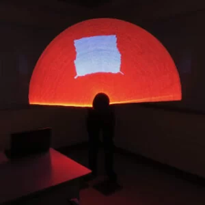
Square mode: In this mode, we want the strip to take the lights based on the position of the lightsaber in air. We imagine a picture of around 125 x 125 pixel in the air. The lightsaber can then be imagined to be making a line on this image. We simply calculate the position of the lightsaber with respect to the image and set up the lights accordingly. In both the square and the star wars mode we compute the cosine and sine values of the pitch angle. This is then multiplied by the LED index we are setting up and check whether the LED index falls inside the expected square or outside and set the color to white or red accordingly.
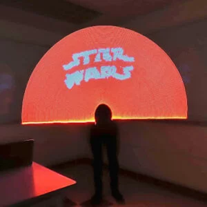
Star Wars: Similar to the square mode but we have an array of the image pre determined using a Python script. Here too, we calculate the position of each LED in the strip w.r.t the image array and write the HSV values accordingly.
Party: We have a sine table created at the beginning of the thread startup to store the range of h in a sinusoidal order. Using these values in tandem with the position of the LED produces a moving rainbow colors on the LED strip.
IMAGE ARRAY
We wrote a simple python script using ‘OpenCV’ library to read an image, convert the dimensions to 125 X 125. This image is then filtered to produce either of the two colors, red or white, for each pixel. This is done so that we only change h component while keeping the s and v uniform throughout and save the memory needed to store the image. The filtered image is then stored in a text file to produce an array of 125 X 125 chars of either 0 or 255. The output text file is then stored and used in the main .c file.
RESULTS
We have been successful in implementing all the components discussed so far in the project. More specifically, we were able to have a start up sequence as close to as seen in the movies (both light and sound effects), produce two different modes of persistence of vision where we can see two images; a square and a star wars logo. And finally, a party mode where we show the entire spectrum of the colors that could be produced with a dot star LED strip.
Although we had hiccups at every step of the project, they were all solved by systematically debugging. The final product is a set up of a PVC pipe (forming the handle) enclosing a polycarbonate tube within which is laid out LED strip. The PVC pipe holds inside the rest of the circuit; a project board embedded with MPU6050, DAC converter, 74LS125 converter, and an audio amplifier along with the PIC32 small board. The power switch and the push button are extended out to the open through holes at the bottom end of the handle. The speaker is set at the base of the handle to produce an echoed sound.
The first prototype of the circuit was made on a breadboard in connection with a PIC32 big board. However, switching the big board with the small board required some changes to the code in tandem with the difference in the connections on the board. Further, we then replaced the breadboard with a project board in a size that could slide into the PVC pipe. With the intent of minimizing the size of the circuitry we have done everything in our capabilities from cutting the project board, sanding the amplifier edges, aligning the wires and checking the measurements of the peripherals at every step.
The software for the project was built in an orderly fashion. First, the structural code for setting the LED strip was worked out. This was to ensure any tests from hereon produced perceivable results. Next, we worked on setting up the Accelerometer and varying the LED colors with the movement in the x axis. At the same time, we worked with the code from lab 1 to produce sound effects similar to the movies using ISR. Once, all the individual modules were up and running we integrated the code into one and set up different modes. The structure of the software then took shape over time with numerous trials and errors to produce the final product.
One of the serious concerns when working on the project was the power consumption consideration of the set up. Our initial estimates of the power drawn by the LED strip alone led us to use batteries with 5V 1A output. However, upon assembling the project the power consumption has increased with the rest of the modules integrated into it. This lead us to use a second battery (seen sticking outside the handle apart from the original one inside the handle) for smooth working of the project.
In the end, the five weeks of collaborative efforts by us has culminated into the working of the skywriter lightsaber as per our expectations.
CONCLUSIONS
We have been successful in meeting our project goals as per our expectations. The project idea was out of a brainstorm session which was then used to find a similar project by Bitluni, a hobbyist embedded systems developer. However, none of the software or hardware designs was used from them except for aiding in a quicker review for the procurement of the modules required. All the individual software modules for running the LED strip, MPU6050 and audio amplifier were all based off skeletal codes available on the ECE 4760 website. They were either written by the professor himself or used in other student projects in previous years. Either way, all the material used in our project was open source.

However, with the experience gained over the course of this project we feel there are a few things we could’ve done differently. For starters, we could’ve started programming on the small board directly instead of Big board and saved us some time in changing the software to align with the different peripheral connections on the boards. Also, although we were careful in selecting different components so as to ensure they fit into the handle we could have spent some extra time in planning to have made the process even smoother. Perhaps, we could’ve used a 3D printed case to ensure the circuit is not disturbed within the handle.
Considering the memory issues we faced when storing the image we had two options; reduce the image size or use external memory. Although we chose to limit the image size by just varying the hue component, we would like to try extending the memory to store more than one image. On the whole, we would like to conclude by thanking Prof. Bruce Land and his team of TA’s for being there with us throughout the project and the course to help us in their every capacity.
code
/*
 * File:        TFT, keypad, DAC, LED, PORT EXPANDER test
 *              With serial interface to PuTTY console
 *              DMA GetMachineBuffer
 *              !!!Modified scheduler!!!
 *
 * Author:      Bruce Land, Alexander Li, Kranthi Kumar M
 * For use with Sean Carroll's Big Board
 * http://people.ece.cornell.edu/land/courses/ece4760/PIC32/target_board.html
 * Target PIC:  PIC32MX250F128B
 */


//This code works for LED and gyro perfectly.
//There's clock on the DAC but we have noise output on speakers. Need to debug that

////////////////////////////////////
// clock AND protoThreads configure!
// You MUST check this file!
#include "config_1_3_2.h"
// threading library
#include "pt_cornell_1_3_2.h"
// yup, the expander
#include "port_expander_brl4.h"

#include "i2c_helper.h"

////////////////////////////////////
// graphics libraries
// SPI channel 1 connections to TFT
#include "tft_master.h"
#include "tft_gfx.h"
// need for rand function
#include <stdlib.h>
// need for sin function
#include <math.h>
////////////////////////////////////

// lock out timer 2 interrupt during spi communication to port expander
// This is necessary if you use the SPI2 channel in an ISR.
// The ISR below runs the DAC using SPI2
#define start_spi2_critical_section INTEnable(INT_T2, 0)
#define end_spi2_critical_section INTEnable(INT_T2, 1)

////////////////////////////////////

/* Demo code for interfacing TFT (ILI9340 controller) to PIC32
 * The library has been modified from a similar Adafruit library
 */
// Adafruit data:
/***************************************************
  This is an example sketch for the Adafruit 2.2" SPI display.
  This library works with the Adafruit 2.2" TFT Breakout w/SD card
  ----> http://www.adafruit.com/products/1480

  Check out the links above for our tutorials and wiring diagrams
  These displays use SPI to communicate, 4 or 5 pins are required to
  interface (RST is optional)
  Adafruit invests time and resources providing this open source code,
  please support Adafruit and open-source hardware by purchasing
  products from Adafruit!

  Written by Limor Fried/Ladyada for Adafruit Industries.
  MIT license, all text above must be included in any redistribution
 ****************************************************/

// string buffer
//char buffer[60];

////////////////////////////////////
// DAC ISR
// A-channel, 1x, active
#define DAC_config_chan_A 0b0011000000000000
// B-channel, 1x, active
#define DAC_config_chan_B 0b1011000000000000
// DDS constant
//#define two32 4294967296.0 // 2^32
//#define Fs 100000


// APA102 datasheet:
// 32 bits of zeros is a start frame
// 32 bits of ones is a stop frame
// LED frame:
// 111_5bit_global_intensity_8bitBlue_8bitGreen_8bitRed
// so 0xff_00_ff_00 is full intnsity green
#define START_FRAME 0x00000000
#define STOP_FRAME  0xffffffff
#define PIXEL_FRAME(i,r,g,b)(0xe0000000 | (((0x1f & (i)))<<24) | ((0xff & (b))<<16) | ((0xff & (g))<<8) | (0xff & (r)))
//#define PIXEL_FRAME(i,r,g,b)(0xe0000000 | ((i)<<24) | ((b)<<16) | ((g)<<8) | (r))
#define FULL_ON 0x1e
#define HALF_ON 0x0f
#define QUAR_ON 0x07

// number of pixels
#define PixelNum 125

//States
#define OFF 0
#define NORMAL 1
#define SQUARE 2
#define PERSIST 3
#define PARTY 4
volatile int state=OFF, button_state=0;

//Gyroscope


typedef struct pixel pixel;
struct pixel{
    char red;
    char green;
    char blue;
    char intensity;
};
// and the whole string
pixel pixel_array[PixelNum];

// string buffer
char buffer[60];

//Gyroscope values
float xGyro;
float yGyro;

////////////////////////////////////
// Audio DAC ISR
// A-channel, 1x, active
#define DAC_config_chan_A 0b0011000000000000
// B-channel, 1x, active
#define DAC_config_chan_B 0b1011000000000000

// audio sample frequency
#define Fs 44000
// need this constant for setting DDS frequency
#define two32 4294967296 // 2^32
// sine lookup table for DDS
#define sine_table_size 256
volatile _Accum sine_table[sine_table_size] ;
// phase accumulator for DDS
volatile unsigned int DDS_phase, FM_DDS_phase ;
// phase increment to set the frequency DDS_increment = Fout*two32/Fs
// For A above middle C DDS_increment =  = 42949673 = 440.0*two32/Fs
#define Fout 110.0
#define FM_Fout 2*110.0


#define MAX_G_VALUE 5000

volatile unsigned int Fnew=0, mode=1;
volatile unsigned int DDS_increment = Fout*two32/Fs , constant; //42949673 ;
volatile unsigned int DDS_const = Fout*two32/Fs;
volatile unsigned int FM_DDS_increment = 5*Fout*two32/Fs ;
// waveform amplitude
volatile _Accum max_amplitude=1500, FM_max_amplitude=1500, FM_out;

// waveform amplitude envelope parameters
// rise/fall time envelope 44 kHz samples
volatile unsigned int attack_time=50000, decay_time=25000, sustain_time=100 ;
volatile unsigned int FM_attack_time=50000, FM_decay_time=15000, FM_sustain_time=100 ;

//  0<= current_amplitude < 2048
volatile _Accum current_amplitude ;
volatile _Accum FM_current_amplitude ;
// amplitude change per sample during attack and decay
// no change during sustain
volatile _Accum attack_inc, decay_inc ;
volatile _Accum FM_attack_inc, FM_decay_inc ;

//== Timer 2 interrupt handler ===========================================
volatile unsigned int DAC_data_A, DAC_data_B ;// output values
//volatile SpiChannel spiChn = SPI_CHANNEL2 ;	// the SPI channel to use
volatile int spiClkDiv = 4 ; // 10 MHz max speed for port expander!!

// interrupt ticks since beginning of song or note
volatile unsigned int song_time, note_time ;

//PushState for debouncing
volatile unsigned int PushState = 0;

volatile unsigned int note[60], counter=0;

volatile int xpos,ypos;

float  values[6],accum_values[3], pitch, roll, sin_pitch, cos_pitch;//low pass filtered accelerometer values


void __ISR(_TIMER_2_VECTOR, ipl2) Timer2Handler(void)
{
    int junk;

    mT2ClearIntFlag();

    // generate  sinewave
    FM_DDS_phase += FM_DDS_increment;
    if(FM_DDS_increment ==0)
    {
        FM_DDS_phase=0;
    }
    //DAC_data += 1 & 0xfff ; // low frequency ramp
    FM_out = (FM_current_amplitude*sine_table[FM_DDS_phase>>24]) ;
    // advance the phase
    DDS_phase += DDS_increment + ((int)FM_out << 16);


    DAC_data_A = (int)(current_amplitude*sine_table[DDS_phase>>24])  + 2048; // for testing sine_table[DDS_phase>>24]

    // update amplitude envelope
    // don't include the envelope for test mode, version 1
    if (state == NORMAL) {
        if (note_time < (attack_time + decay_time + sustain_time)){
            current_amplitude = (note_time <= attack_time)?
                current_amplitude + attack_inc :
                (note_time <= attack_time + sustain_time)? current_amplitude:
                    current_amplitude - decay_inc ;
        }
        else {
            current_amplitude = max_amplitude;;
        }

        if (note_time < (FM_attack_time + FM_decay_time + FM_sustain_time)){
            FM_current_amplitude = (note_time <= FM_attack_time)?
                FM_current_amplitude + FM_attack_inc :
                (note_time <= FM_attack_time + FM_sustain_time)? FM_current_amplitude:
                    FM_current_amplitude - FM_decay_inc ;
        }
        else {
            FM_current_amplitude = 0 ;
        }
    }
    if(state == OFF) current_amplitude = 0;
    else {
    current_amplitude=max_amplitude;
    }

    if(state == PARTY) constant = 100000;
    else constant = 10000;

    if(xGyro>0){
    DDS_increment = DDS_const + xGyro*constant;
    }
    else DDS_increment = DDS_const - xGyro*constant
            ;
     // test for ready
     while (TxBufFullSPI1());

    // reset spi mode to avoid conflict with expander
    //SPI_Mode16();
    // DAC-A CS low to start transaction
    mPORTBClearBits(BIT_4); // start transaction
     // write to spi1
    WriteSPI1(DAC_config_chan_A | (DAC_data_A & 0xfff) );
    // fold a couple of timer updates into the transmit time

    // test for done
    while (SPI1STATbits.SPIBUSY); // wait for end of transaction
    // MUST read to clear buffer for port expander elsewhere in code
    junk = ReadSPI1();
    // CS high
    mPORTBSetBits(BIT_4); // end transaction
    note_time++;
}

// === display the LEDs ===========================================
// copies the contents of pixel_array to SPI
void write_pixels(void){

    // start frame
    WriteSPI2(START_FRAME);
    // wait for end of transaction
    while (SPI2STATbits.SPIBUSY);

    int i;
    //payload
    for (i=0; i<PixelNum; i++){
        WriteSPI2(PIXEL_FRAME(pixel_array[i].intensity, pixel_array[i].red, pixel_array[i].green, pixel_array[i].blue));
        // wait for end of transaction
        while (SPI2STATbits.SPIBUSY);
    }
    //stop frame
    WriteSPI2(STOP_FRAME);
    // wait for end of transaction
    while (SPI2STATbits.SPIBUSY);
}

// === write a RGBI value to the pixel array =======================
void set_pixel_rgb(int i, char r, char g, char b, char intensity){
    if (i<0 || i>=PixelNum) return ;
    pixel_array[i].intensity = intensity  ;  //enforce max
    pixel_array[i].red = r   ;
    pixel_array[i].green = g  ;
    pixel_array[i].blue = b ;
}

// === write a HSVI value to the pixel array =======================
void set_pixel_hsv(int i, float h, float s, float v, char intensity){
    float C, X, m, rp, gp, bp ;
    unsigned char r, g, b ;
    // index range check
    if (i<0 || i>=PixelNum) return ;
    // hsv to rgb conversion from
    // http://www.rapidtables.com/convert/color/hsv-to-rgb.htm
    C = v * s;
    //X = C * (1 - abs((int)(h/60)%2 - 1));
    // (h/60) mod 2  = (h/60 - (int)(h/60))
    X = C * (1.0 - fabsf(fmodf(h/60.0, 2.0) - 1.));
    m = v - C;
    if      ((0<=h) && (h<60))   { rp = C; gp = X; bp = 0;}
    else if ((60<=h) && (h<120)) { rp = X; gp = C; bp = 0;}
    else if ((120<=h) && (h<180)){ rp = 0; gp = C; bp = X;}
    else if ((180<=h) && (h<240)){ rp = 0; gp = X; bp = C;}
    else if ((240<=h) && (h<300)){ rp = X; gp = 0; bp = C;}
    else if ((300<=h) && (h<360)){ rp = C; gp = 0; bp = X;}
    else                         { rp = 0; gp = 0; bp = 0;}

    r = (unsigned char)((rp+m)*255) ;
    g = (unsigned char)((gp+m)*255) ;
    b = (unsigned char)((bp+m)*255) ;

    pixel_array[i].intensity = intensity  ;  //enforce max
    pixel_array[i].red = r   ;
    pixel_array[i].green = g  ;
    pixel_array[i].blue = b  ;
}

// === thread structures ============================================
// thread control structs
// note that UART input and output are threads
static struct pt pt_timer, pt_gyro;


// === Timer Thread =================================================
// update a 1 second tick counter
int position=0, dir=1,img_column=0;
#define DDS_sample_time 30

// variables for red snake
volatile int start = 0, end = 4, snake_counter = 0;

//variables for sound
volatile int sound_count = 0, count_start=0;

static PT_THREAD (protothread_timer(struct pt *pt)){
    PT_BEGIN(pt);

     PT_YIELD_TIME_msec(1000) ;

      static int i ;
      static int sine[256], c[256] ;
      static float h, s, v, m[256];
      // with a 16 bit DDS and 8-bit sine table index
      // frequency of sine output is related to increment as
      // inc = Fout * 2^16 * DDS_sample_time
      // e.g. for 2 Hz and sample time 0f 30 millisec:
      // inc = 2 * 2^16 * 0.030 = 3932
      // or an increment of about 2000 per Hz. (with 30 mS sample time)
      static unsigned short dds_inc_r=1500, dds_inc_g=1500, dds_inc_b=500, dds_inc_m=600;
      static unsigned short dds_acc_r, dds_acc_g, dds_acc_b, dds_acc_m;
      static char r,g,b,intensity;
      // set up DDS tables
      // 256 entries of 8-bits each
      for(i=0; i<256; i++){
        sine[i] = (int)(120.*sin((float)i*6.28/256.)+ 120);
        c[i] = (int)(120.*cos((float)i*6.28/256.)+ 120);
        m[i] = (360.*((float)i/256.)); //  i to h in degrees
      }

      static index = 0; //for looping through image array


      while(1) {
        // yield time
        PT_YIELD_TIME_msec(2);
        //Uncomment these if you want to use party mode

        // DDS phase incrementers
        dds_acc_r += dds_inc_r ;
        dds_acc_g += dds_inc_g ;
        dds_acc_b += dds_inc_b ;
        dds_acc_m += dds_inc_m ;


        // Toggle mode
        if( mPORTAReadBits(BIT_0) && button_state == 0) {

            if(state == PARTY){//turn off sequence
                state = OFF;
            }
            else { //toggle
                state++;
            }
            button_state = 1;
            note_time=0;
            count_start=0;
        }
        if(!mPORTAReadBits(BIT_0) && button_state == 1){
            button_state=0;
        }


        if(start > PixelNum) {
            start =0;
            end = 4;
        }
        else if(start < 0) {
            start =0;
            end = 4;
        }
        start = start + (int)xGyro/2;
        end = end + (int)xGyro/2;


        float pitch_temp = pitch;
        sin_pitch = sin(pitch_temp);
        cos_pitch = cos(pitch_temp);
        //SETTING THE LEDS
        for(i=0; i<PixelNum; i++){
            // shift dds_acc by 8 for index into table
            // add array index for motion
            // mask with 0xff for moduluo 256 operation

            switch(state){
                case OFF:
                    h = s = v = 0.0;
                    break;
                case NORMAL:

                    if(i<count_start) {
                        v = 1.0;
                        s = 1.0;
                        h = 0.0;
                    }
                    else h = s = v = 0.0;

                    break;
                case SQUARE:
                    ypos = (int)((float)i * sin_pitch);
                    ypos = PixelNum-1 - ypos;
                    xpos = (int)((float)i * cos_pitch);

                    if(values[2]>0){
                        xpos = 62-xpos;
                    }
                    else xpos = 62 + xpos;


                    h=0.00;
                    v=1.0;

                    if(xpos > 30 && xpos < 90 && ypos > 30 && ypos <90){
                        s=0.0;
                    }
                    else s = 1.0;

                    break;

                case PERSIST:
                    ypos = (int)((float)i * sin_pitch);
                    ypos = PixelNum-1 - ypos;
                    xpos = (int)((float)i * cos_pitch);

                    if(values[2]>0){
                        xpos = 62-xpos;
                    }
                    else xpos = 62 + xpos;


                    h=0.0;
                    v=1.0;
                    if(xpos<0 || xpos >PixelNum -1 || ypos < 0 || ypos > PixelNum-1){
                        s=01.0;
                    }
                    else{
                        if(img_s[ypos][xpos]== 0){
                            s=1.0;
                        }
                        else s = 0.0;
                    }


                    break;
                case PARTY:
                   h = m[((dds_acc_m>>8)+i) & 0xff];
                    v = 1.0;
                    s = 1.0;


                    break;

                default:

                    h = s = v = 0.0;
                    break;
            }

            intensity = QUAR_ON ;
            set_pixel_hsv(i, h, s, v, intensity);
        }
        count_start +=2;
        if(img_column<100 && state == PARTY) img_column +=1;
        else if (state == PARTY) img_column=99;
        write_pixels();


      } // END WHILE(1)
  PT_END(pt);
} // timer thread

static PT_THREAD (protothread_gyro(struct pt *pt)){
    PT_BEGIN(pt);

    PT_YIELD_TIME_msec(300);

    while(1) {
        PT_YIELD_TIME_msec(2);


        // Read the Gyro values
        // Read data from IMU in format
        // {xAccel, yAccel, zAccel, xGyro, yGyro, zGyro}

        readImuValues(values);

        // Parse the IMU data
        xGyro  = values[3];
        yGyro  = values[4];

        // creating a digital low pass filter
        accum_values[0] = accum_values[0]*0.75 + .25* values[0]/MAX_G_VALUE;
        accum_values[1] = accum_values[1]*0.75 + .25* values[1]/MAX_G_VALUE;
        accum_values[2] = accum_values[2]*0.75 + .25* values[2]/MAX_G_VALUE;


         pitch = atan2((-accum_values[1]) , sqrt(accum_values[0] * accum_values[0] + accum_values[2] * accum_values[2]));//computes the pitch


        if (pitch > 1.57){
            pitch = 1.57;
        }
        else if (pitch < -1.57){
            pitch = -1.57;
        }


    }


    PT_END(pt);
}

// === Main  ======================================================
void main(void) {


  //SETUP ISR FOR SOUND
  OpenTimer2(T2_ON | T2_SOURCE_INT | T2_PS_1_1, 908); //<==========breaks the SPI for LED
  ANSELA = 0; ANSELB = 0;
  ConfigIntTimer2(T2_INT_ON | T2_INT_PRIOR_2);
  mT2ClearIntFlag(); // and clear the interrupt flag

  PPSOutput(2, RPB1, SDO1);

  // control CS for DAC
    mPORTBSetPinsDigitalOut(BIT_4);
    mPORTBSetBits(BIT_4);

     // divide Fpb by 2, configure the I/O ports. Not using SS in this example
    // 16 bit transfer CKP=1 CKE=1
    // possibles SPI_OPEN_CKP_HIGH;   SPI_OPEN_SMP_END;  SPI_OPEN_CKE_REV
    // For any given peripherial, you will need to match these
    // clk divider set to 4 for 10 MHz
    SpiChnOpen(SPI_CHANNEL1, SPI_OPEN_ON | SPI_OPEN_MODE16 | SPI_OPEN_MSTEN | SPI_OPEN_CKE_REV , 4);
   // end DAC setup
    // build the sine lookup table
   // scaled to produce values between 0 and 4096
   int i;
   for (i = 0; i < sine_table_size; i++){
         sine_table[i] = (_Accum)(sin((float)i*6.283/(float)sine_table_size));
    }

   // build the amplitude envelope parameters
   // bow parameters range check
	if (attack_time < 1) attack_time = 1;
	if (decay_time < 1) decay_time = 1;
	if (sustain_time < 1) sustain_time = 1;
	// set up increments for calculating bow envelope
	attack_inc = max_amplitude/(_Accum)attack_time ;
    FM_attack_inc = max_amplitude/(_Accum)attack_time ;
	decay_inc = max_amplitude/(_Accum)decay_time ;
    FM_decay_inc = decay_inc*(0.80/0.98) ;
  // === config threads ==========
  // turns OFF UART support and debugger pin, unless defines are set
  PT_setup();

  // === setup system wide interrupts  ========
  INTEnableSystemMultiVectoredInt();


    //LED SPI
    SpiChnOpen(2, SPI_OPEN_ON | SPI_OPEN_MODE32 | SPI_OPEN_MSTEN | SPICON_CKP, 4);
    // SCK2 is pin 26
    // SDO2 (MOSI) is in PPS output group 2, could be connected to RB5 which is pin 14
    PPSOutput(2, RPB5, SDO2);


  // init the threads
  PT_INIT(&pt_timer);
  PT_INIT(&pt_gyro);

  //Init button
  mPORTASetPinsDigitalIn(BIT_0);

  // === setup I2C  ========
  // PBCLK 40Mhz, FSCK 400kHz -> 0x02C I2CxBRG
  // src: table 24-2
  // https://people.ece.cornell.edu/land/courses/ece4760/PIC32/index_i2c.html
  OpenI2C1(I2C_ON, 0x02C);


  // Take the Gyro out of sleep mode
    char data[] = {0};
    i2c_write(0x6b, data, 1);

    // Set the gyro sensitivity to 131 lsb/(degrees/second))
    i2c_write(0x1b, data, 1);

    // Calibrate the gyroscopes (robot must be stable on flat surface)
    calibrateGyros();


  // round-robin scheduler for threads
  while (1){
      PT_SCHEDULE(protothread_timer(&pt_timer));
      PT_SCHEDULE(protothread_gyro(&pt_gyro));
  }
} // main

// === end  ======================================================
Python script for image array
"""
Author: Kranthi Kumar M
Convert image to HSV text file

"""

import cv2
import numpy as np

# Reads the image
img = cv2.imread('star_wars_final1.jpg')

# Converts to HSV color space
img = cv2.cvtColor(img, cv2.COLOR_BGR2HSV)

dim = (125,125)
img = cv2.resize(img,dim)
# Shows the image


f = open('HSV_star_wars.txt', 'w+')

print(img.shape)

temp=0.0000

for i in range(125):
    for j in range (125):
        img[i][j][2]=255
        img[i][j][0]=0
        temp=float(img[i][j][1])
        if(temp<127):
            img[i][j][1]=0
        else:
            img[i][j][1]=255
        f.write(str(img[i][j][1]))
        if(j != 124):
            f.write(', ')
    f.write('},\n{')

abc = np.asarray(img[:,:,1])


np.savetxt("hsv_red.csv", abc, delimiter=",", fmt='%d')

'''
for contents in img:
    f.write(str(contents))
'''
f.close()

print(img[0][0][2]/2)

img = cv2.cvtColor(img, cv2.COLOR_HSV2BGR)
cv2.imshow('image', img)
cv2.waitKey(0)
cv2.destroyAllWindows()
Source: THE SKY WRITER
About The Author
Muhammad Bilal
I am a highly skilled and motivated individual with a Master's degree in Computer Science. I have extensive experience in technical writing and a deep understanding of SEO practices.