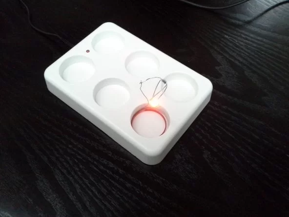
Some time ago I bought some Electric Tea Lights that are charged using a wireless charger. This charger has a power LED that shows when the Lights are charged. After 10 hours of charging the charges switches off. It seemed, however, that there is an issue with the charger since the power LED that shows if the charger is active is always on, albeit a bit brighter when it is charging but this is hardly visible. In fact, you can hardly see if the power LED is on at all. I mentioned it to the manufacturer and I received a new charger but it had exactly the same problem
So I wanted to create something that shows if the charger is active when I need to charge my new Tea Lights. Of course I could try to replace the LED in the charger but I did not want to open it because of warranty issues. I had some older Tea Lights that no longer worked due to the battery being too old and my idea was use such a Tea Light to show that the charger is active by putting this Tea Light in one of the locations where the Tea Lights are charged.
I could have made a simple on-off Light but since it is Tea Light which normally has a candle effect, I decided to give it a candle effect too. I used the housing and the coil of an old Tea Light and created a candle effect using a LED and a PIC microcontroller. Instead of a PIC you can of course use an Arduino.
Step 1: Required Components
You need to have the following components for this project:
- A piece of breadboard
- PIC microcontroller 12F615
- Diode 1N4148
- 47 uF/25V electrolytic capacitor
- 100nF ceramic capacitor
- 33k and 470 Ohm resistors
- Orange LED
- The housing and the coil of an old Tea Light
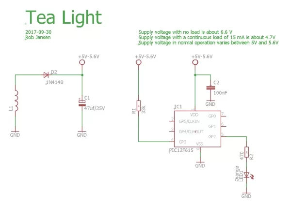
See the schematic diagram on how to connect the components.
Step 2: First Some Analysis
Before I started the project I needed to know if the coil in the Tea Light would provide sufficient power for the circuit to work. I connected an oscilloscope to the coil when it was in the charger. The output of the coil is shown in the screenshot.
The charger generates a pulse with a frequency of about 36 kHz and generates a voltage in the coil of about 8 Volt peak. In the schematic diagram this signal is rectified with the Diode and Electrolytic capacitor. Some measurements gave the following results:
- Without any load the rectified supply voltage is around 6.6 Volt
- When connecting a LED and a resistor, drawing a current of 13 mA, the supply voltage drops to about 4.7 Volt. The photo shows a setup of this test.
These measurements showed me that it was possible to supply the circuit since most current goes through the LED and not the PIC.
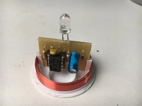
Step 3: Building the Electronics and the Tea Light

First you need to remove the bottom part from the Tea Light using a small saw. Be careful since you might damage the coil if you saw too deep. The pictures show the saw I used and the result with the bottom plate removed.
The only parts you need are the housing and the coil.
You can build the circuit on a breadboard that has the size of the original electronics. In the picture you can see the circuit as I build it on the breadboard and how it fits in the housing of the old Tea Light.
After assembling and testing the circuit you can glue the bottom part back to top part of the housing.
Step 4:
As already mentioned, the software is written for a PIC12F615. It was written in JAL. Since I did not use any specific libraries the total code size is only 165 bytes which fits easily in the 1k program flash memory this specific controller has.
To create a candle effect I use Pulse Width Modulation (PWM) to vary the intensity of the LED. Pulse Width Modulation has been described several times, e.g. in this Arduino Article: https://www.arduino.cc/en/Tutorial/PWM
PIC and Arduino have special PWM hardware on board that makes it simple to generate this PWM signal. A Timer is used to create the PWM period and a register is used to vary the on-time of the LED during this period of time, the so called pulse width. In this project the PIC runs on an internal clock frequency of 4 MHz, generating a PWM period of 4,1 ms which equals a frequency of 244 Hz. This frequency is not visible for the human eye. The main program increases and decreases the pulse width randomly which creates the candle effect.
The JAL source file and the Intel Hex file are attached.
The video shows the operation of the Tea Light. When the charger is switched on, the Tea Light starts flickering. Since there is no battery in the Tea Light it stops as soon as the charger switches off or when the Tea Light is removed from the charger. As you can see in the video, the light from the power LED is hardly visible. The good thing is that it resulted in this nice project.
Have fun building your own project and looking forward to your reactions.
Attachments
Source: Tea Light Charger Monitor
About The Author
Muhammad Bilal
I am a highly skilled and motivated individual with a Master's degree in Computer Science. I have extensive experience in technical writing and a deep understanding of SEO practices.