Introduction
When I set, some time ago, about working with a PIC 16×84, I had immediately to face the problem to have a permanently and stably working circuit, without mounting the PIC on a prototype board every time. Searching on the net, I didn’t find anything really complete for a PIC 16F84 / 16C84; I therefore decided to personally build an Evaluation Board allowing to operate with this microcontroller in the RC and XT modes, that is with a clock generated by resistor-capacitor net or by a crystal, but above all allowing to interface the PIC with external circuits in a very versatile and in the same time reliable way. So the Evaluation Board was born. I present here an improved version of it, which adds some functions to the original ones, but, how to say, I am attached to the first version.
If you are interested in microcontrollers of higher families, you could take a look at the PIC 16F874 / 16F87 development board on this site.
Disclaimers and acknowledgements
This project is entirely personal, both in planning and in realising; an acknowledgement goes to the software allowing me to draw the printed circuit layout. The program is PCB Elegance v 2.0 (I have the FREE 200 pins limited version), realised by MERCO Electronics, which has authorized me by e-mail also to non-personal purposes.
Microchip and PIC are registered trademarks.
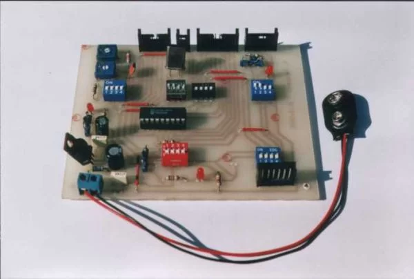
Attenzione: la versione della F.F. Evaluation Board presentata in questa pagina è la 3.0; si tratta di un circuito che è simile a quello della versione 2.0, riportata in fotografia, ma con alcune migliorie. La basetta visibile nell’immagine ospita un PIC 16F84 a 4 MHz, ma è compatibile anche con il PIC 16C84. Il circuito versione 2.0 è perfettamente funzionante sin dal Febbraio 2000 (from here the name F.F.), ma per mancanza di tempo sul nuovo circuito stampato i componenti non sono ancora stati montati. Anche se le modifiche sulla carta non dovrebbero incidere sulla possibilità di un corretto funzionamento, si tenga presente anche questa avvertenza. Indicheremo questa versione come “V. 3.0 Beta”. Nel momento in cui anche la nuova versione sarà stata realizzata e collaudata provvederò all’aggiornamento di questa pagina.
Note: Although it’s theoretically possible to use other forms of supply, this Evaluation Board has been projected to receive supply from a 9V battery and interfaced only with circuits with low voltage batteries supply.
In any case, be always aware of what you are doing!
Being this material at free disposal of whoever desires it, it is absolutely forbidden any form of use for commercial purposes.
It is also forbidden any change to the circuit if not for didactic or purely personal purposes; if this is the case, they must not take anyway to any form of direct or indirect profit.
If, in whichever way, you wish to divulge such changes, it is compulsory to ask a written permit to the author of this article (also by e-mail, at [email protected]).
The circuit’s layout and all the informations contained in this page are supplied “as they are”, without any form of warranty. I don’t assume of course any direct or indirect responsibility for direct or indirect damages to things or person coming from informations got from this article.
Suggestions of any kind to allow me to improve the circuit are well accepted.
Circuit’s characteristics and description
I immediately say that this circuit is not a PIC programmer, but it can be easily interfaced with one of the many circuits of that kind that it is possible to find, allowing this way the user not to remove the microcontroller from the Evaluation Board while programming it.
As previously said, the photo you can watch at the beginnng of this page is concerning the circuit in the February 2000 version, the one preceding the 3.0 described in these pages; anyway, the two version do not differ in a huge way, so the image is similar to the one you could obtain realising the F.F. Evaluation Board v. 3.0.
The Evaluation Board is built on a single side breadboard, so to be realised with not too many difficulties. The most part of working possibilities are selectable by 4-ways and 6-ways dip-switches (in the photo only the 4-ways dip-switches); it is possilble to carry to the breadboard external power and I/O signals, or to get them from it, as well as carrying to the chip the programming signals; all connections with the external world should be realised using the connectors you can find on circuit’s edges.
Before going on with the circuit’s description, we introduce here an operative remark.
Remark for switches and connectors’ pins identification
References to a particular switch belonging to the dip-switch Sx will be made by Sx-n, where n and x are integer numbers; the same convention for connectors JPx. In particular, a reference to the switch Sx-1 points out the first switch of the dip.switch Sx starting counting from top in the design where all components, bridges and tracks are reported; the same meaning when referring to connectors JP. As an instance, you can see that S10-6 is not connected to ny track; when opened, S4-4 is only connected to S4-2 and to the PIC’s pin n.15; when closed, it is connected to JP2-2 and JP6-2, too.
Remark: in this text I will refer almost only to JP1, JP2, JP3, JP4; it is understood that I refer also to JP5, JP6, JP7, JP8 respectively, as homologous elements of the two sets are connected together pin by pin.
Let’s now deal again with characteristics of the Evaluation Board.
Supply: the circuit has been projected for a 9V battery as a power supply, but it is also possible to use an unregulated 7-15V DC source (a 7805 supplies 5V regulated to the PIC, possibly to a programmer and also to an external circuit), or supply from an external circuit through JP4 – S5 (please read Microchip datasheets for suitable range).
/MCLR pin: it is possible to control it from an external circuit or by a programmer, to connect it with a pull-up directly to Vdd, or even to Vss through a capacitor so to realize a Power On circuit (already present in the PIC); there is also the possibility to reset the PIC by the S9 switch (not viewable in the picture).
Connection from and to external circuits of Vdd, Vss, /MCLR: connection from or to any external circuit of Vdd, Vss, /MCLR (this last one whichever the power source is); connection of Vdd and Vss from or to any programmer.
Clock generation: 4 MHz crystal, RC mode with two potentiometers for oscillation around 1 MHz and 100 KHz;
possibility of receiving clock signal from an external circuit or to send to it the reference oscillation.
Possibility of programming the PIC directly on the Evaluation Board: it is possibile to connect the board to a programmer by a 5 wires connector, with the possibility to supply power to the programmer or to receive power from it.
Connection from and to external circuits of I/O pins: all I/O pins are connected to connectors to interface the PIC with an external circuit. In the photos you can see only connectors for plugs, while in the new version you can find both those ones and SIL connectors for wiring.
Spie alimentazione: tre led inseribili singolarmente mediante jumpers indicano la presenza di alimentazione in parti diverse del circuito e ricordano di prestare attenzione ad evitare conflitti elettrici fra le possibili sorgenti di alimentazione.
Esiste anche un diodo per la protezione dall’inversione della polarità di alimentazione al 7805 (ma non per le altre sorgenti).
Qualche applicazione
Per quanto riguarda le possibili applicazioni, la basetta consente di avere un circuito di base sicuramente funzionante e facilmente interfacciabile, con conseguente possibilità di dedicarsi alla messa a punto del programma e del circuito da sviluppare.
Personalmente ho utilizzato la versione 2.0 per costruire, tra l’altro, un frequenzimetro di L.F. (fino a circa 18 KHz), un cardiofrequenzimetro (mediante coppia led-fotoresistore posta in prossimità della cute), entrambi con visualizzazione su display 7 segmenti, una interfaccia per la comunicazione con un mouse PS/2.
Selection of working mode
As previous said, the selection of working mode is realized by dip-switches.
For more detail: PIC16F84 Evaluation Board
About The Author
Ibrar Ayyub
I am an experienced technical writer holding a Master's degree in computer science from BZU Multan, Pakistan University. With a background spanning various industries, particularly in home automation and engineering, I have honed my skills in crafting clear and concise content. Proficient in leveraging infographics and diagrams, I strive to simplify complex concepts for readers. My strength lies in thorough research and presenting information in a structured and logical format.
Follow Us:LinkedinTwitter