The device is based on a GSM/GPRS module with included GPS. Its main function is to detect and communicate its own geographical position using, on the choice, the cellular phone reference system or the GPS. Its small dimensions are due to the use, for the first time, of a GSM/GPRS module integrating the GPS receiver. That is the SIM908 a recent product by SIMCOM.]
Circuit schematic of the localizer
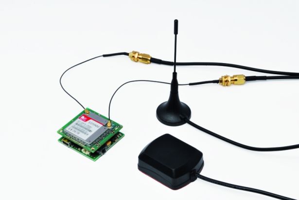
The circuit of the localizer is build around two boards, one with the SIM908 on board and the second one including the microcontroller and the battery charger for the lithium battery. To get the GPS working will be necessary to complete the localizer circuit with an appropriate antenna.
The circuit includes the mother board, mounting the microcontroller and its circuitry, and the daughter board mounting the communication module, the block named GSM in the schema. The reference numbers associated to the contacts on the GSM block correspond to the pins of the connector linking the daughterboard to the motherboard.
The program running in the microcontroller U1, one PIC18LF6722, waits for an incoming event or for the button P1 being pushed. While the button is pressed the line RB1, provided with internal pull-up resistor, switches from logical level 1 to the logical level 0,
In case of incoming of an SMS message, the program reacts depending on the content of the message that could be a configuration message or a geographical position request.
Let focus on the process aimed to retrieve the geographical position, that is quite the same in both cases of manual request and P1 pushing (alarm or S.O.S.). After the request has been detected, the program in the PIC microcontroller sends commands to the cellular module in order to have it connected to Internet in GPRS mode. Then connects to the Google Maps server and sends a request of position based on the identification of the cell the SIMCom module is connected to; then again loop waiting for data on the RX channel of the UART. While got data back with the position (Latitude and Longitude) and accuracy, it is a composed string with the appropriate link to Google Maps and sent to the requesting phone, or to the phone number stored in memory coupled to the alarm function.
If the cellular phone is an Android Smartphone or an iPhone, the link received in the SMS can open Google Maps directly on the area where the localizer is present. In the other cases the message contains the coordinates and other data.
The GSM module is managed by the microcontroller using the lines: RF1 (pin 8 on connector) through which it detects the incoming calls through the Ring Indicator (RI), RC7/RX1 (pin 14 on the cellular board); these last two are the lines, respectively, of reception and transmission of the UART used for receiving and sending SMS messages. The same two lines are used for managing the SIM908, unless the reset and power supply lines. Power supply is controlled by line RC2 that affects pin 1 of the cellular module in order to turn ON and OFF the SIM908 and to enable the phone after initialization. Lines cited before are common to the GSM and GPS section of SIM908.
For more detail: Localizer with SIM908 module using PIC18LF6722
About The Author
Ibrar Ayyub
I am an experienced technical writer holding a Master's degree in computer science from BZU Multan, Pakistan University. With a background spanning various industries, particularly in home automation and engineering, I have honed my skills in crafting clear and concise content. Proficient in leveraging infographics and diagrams, I strive to simplify complex concepts for readers. My strength lies in thorough research and presenting information in a structured and logical format.
Follow Us:LinkedinTwitter