Heavy duty portable charger for usb devices (phones, iPad, etc.)
Ever needed to charge your phone on the go? Can’t find a wall socket to charge your iPod?
Whenever I’m away from home for an extended period of time, I would charge my phone and mp3 player from my laptop. This way, I get about 3 or 4 full charges out of the laptop battery and I could leave the phone and mp3 player chargers at home. But carrying around a laptop just to charge a phone and mp3 player seemed a little excessive.
Later on I discovered the now hugely popular Minty Boost , a small battery-powered device for charging USB devices. However, after making my own I found that the two AA batteries used in the Minty Boost just didn’t have enough juice for what I needed (a couple of 2000mAh AA cells gave me about half a charge on my phone before giving out).
So I decided to combine the capacity of a laptop battery with the portability of the Minty Boost: A heavy duty portable charger.
The device is based around a DC/DC boost circuit, a microcontroller (I used a PIC), and a handful of 18650 lithium-ion cells. Laptop batteries usually contain 8 of these cells (although I notice my netbook only uses 3, which explains the dismal battery life). I harvested the batteries for this device from an old Dell laptop battery, but you can buy 18650 cells cheaply on ebay, (you can see one in the top right of the picture below),.
Note: for this instructable, you will require experience with circuit building, programming and using microcontrollers. I have included my source code for the PIC12F683, but the same circuit applies to Atmel or other microprocessors.
Note2: While I have designed the simple circuit from scratch, the general principles behind such circuits are well established, I am sure many people who have built such devices will have arrived at very similar circuits. Infringement is not intended.
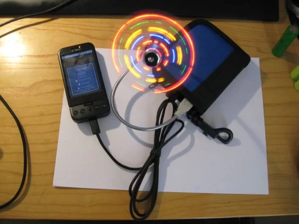
Pictured is the final device charging my phone and running a USB fan at the same time, this one contains 4 18650 cells, has two USB sockets and is built into an 8cm CD wallet, which I found was a perfect size.
Comparison with Minty Boost-type devices
Those of you familiar with Minty Boost or similar devices might point out that the benefits of the AA batteries are that, being ubiquitous, you could simply go out and buy some more if you run out of power; and that this is unfortunately not the case with 18650 cells.
My argument for using the 18650 cells are: Firstly, having built and used a Minty Boost-type device for a while, I can say that I’d rather just wait until I get back to the hotel than go out and spend money buying more cells (which would give me half a charge anyway). Secondly, lithium-ion has about 3 times the energy density compared with NiMH cells, so for the same weight in batteries, you should be able to get by until you reach a power point before having to replace them.
So both 18650 and AA have their own advantages, here’s a comparison between a Minty Boost-type device and the heavy duty charger:
Minty-Boost:
Battery type: 2 * AA
Approximate energy capacity*: 20kJ
Pros:
– Small
– Uses readily available AA batteries
18650 heavy duty charger:
Battery type: 4 * 18650 Li-ion
Approximate energy capacity*: 128kJ
Pros:
– over 6 times the energy capacity
– higher current output**
* energy capacity calculated using equation: no. batteries * battery voltage * battery Ah capacity * 3600 = energy capacity
** I’ve never tested maximum current output of the device, there are some issues with heat dissipation at higher output powers that limit the effective output current.
Pictured is the difference in scale between the two devices, alongside their batteries. On the left is my own rendition of a Minty Boost-type device. built into a case that used to hold my cuff-links, running of 2 AA batteries and an LT1303 DC/DC chip (which I believe gives slightly less current out than the MAX756 of the Minty Boost).
The circuit: overview
The heart of all these devices is the humble DC/DC boost circuit, this is essentially a transformer for DC power sources, it will step up a DC voltage (say 2.4V from two AA batteries) to a higher DC voltage (say 5V for USB charging).
One shortfall of the Minty Boot-type devices is the use of a micropower DC/DC boost chip. These ICs pack the transistor, sensors and oscillators needed for the DC/DC circuit into a neat 8-pin package that you can quickly build a circuit with. Unfortunately, because they’re “micropower”, they’re not designed to output higher power, but luckily they usually have enough to meet the 100 – 200mA required for USB.
To get around this, I’ve decided to build the DC/DC boost circuit myself. The downside of not using a pre-packaged IC is that I have to build my own control circuit to control the DC/DC boost circuit. The upside is that now I can choose components with a higher power rating so I can get more output current.
I’ve had to split the circuit in two halves to get them to display large enough to see the text, the next few sections will explain component selections.
Components: part 1
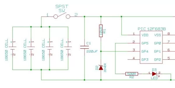
The component list and circuit is as follows, from left to right
18650 batteries (and battery clips):
I am using 4 18650 batteries in parallel, generally speaking you should probably avoid doing this since there is some overheating risk as the cells try to discharge through each other. If you want to ensure safety, you could add a diode after each cell so that they play nice. These lithium-ion cells have a terminal voltage of 4.2V when fully charged, dropping down to a minimum of 3V. Any number of cells in parallel is ok. You can also use AA cells, but you’d probably want to have them stacked in twos to create 2.4 – 3V. Note: however you decide to arrange the batteries, do not exceed 5V, the DC/DC boost circuit can only BOOST a voltage, not reduce it. To reduce voltage, you will need a DC/DC Buck circuit instead.
For battery clips, I cut and bent some paper clips.
a switch (SW): this is the power switch, it’s optional since you could leave it switched on all the time, the circuit doesn’t draw much power if it’s left switched on with nothing plugged in.
smoothing electrolytic capacitor (C1): I use 220uF capacitors, this is for smoothing, so anything in the 100s of uF will do, Minty Boost uses 100uF.
a voltage reference diode (D2) + resistor (R1): you will need something like a low power 2.7V zener diode to give you the correct voltage reference for the microcontroller. If you don’t have any zener diodes, you could use a normal diode like I did (if you use a normal diode, you need to connect it the other way round to the zener diode in the diagram). I (and also the supplied code) actually used a 1N4001 general purpose diode and a 10kOhm resistor. You can also use a voltage reference IC
an LED (D3) + resistor (R2): any LED and suitable resistor is fine
a microcontroller: I used a PIC12F683, these are great little chips for simple circuits because they can run off any voltage between 2V and 5.5V
For more detail: Heavy duty portable charger for usb devices (phones, iPad, etc.) using PIC12F683


