Summary of WITHOUT USE ULTRASONIC SENSORS PARKING SENSOR CIRCUITS PIC12F675
Summary: A DIY parking aid using a capaciflector (capacitive proximity) sensor instead of ultrasonic sensors. An aluminum strip on the bumper forms a capacitor with the car chassis; an oscillator tied to a PIC12F675 measures frequency shifts as objects approach. The PIC counts pulses, provides three distance thresholds with distinct beep patterns, and supports optional LED bar output via a 4094. Files provided include schematics, PCB, PIC hex/source, and a capaciflector patent. The design detects people and objects up to ~70 cm and is powered from the reverse lamp 12V.
Parts used in the Parking Sensor Circuit with PIC12F675:
- PIC12F675 microcontroller (or PIC with T1CKI input such as 16F628)
- Oscillator circuit components (resistors, capacitors, transistor as per schematic)
- TL082 dual operational amplifier (or equivalent dual op amp such as LM324)
- Adhesive aluminum tape (sensor strip)
- PVC pipe or strip to isolate aluminum tape
- PCB (SMD layout provided) or perfboard components
- Preset (trim potentiometer) for sensitivity/frequency adjustment
- Power supply connections to 12V reversing light
- Connector to car chassis (ground)
- Speaker or piezo buzzer for beep patterns
- 4094 shift register (optional) and associated clock/data connections for LED bar
- LEDs and resistors (for optional LED distance bar)
- Miscellaneous passive components: resistors, capacitors, transistors
- SMD or through-hole equivalents as per provided PCB and schematic
Generally, parking sensors, ultrasonic sensors are used in the circuits used in the sensor circuit is shared very different handmade, fitted to the rear bumper of the car “capacitive proximity sensor” was called to…Electronics Projects, Without use Ultrasonic Sensors Parking Sensor Circuits PIC12f675 “microchip projects, microcontroller projects, “
Generally, parking sensors, ultrasonic sensors are used in the circuits used in the sensor circuit is shared very different handmade, fitted to the rear bumper of the car “capacitive proximity sensor” was called to the construction’s pictures and information.
In this opportunity, I offer my first prototype of a system of parking aid for cars, with the novelty that does NOT work by ultrasound but by a system called “capaciflector”
It took me 6 months of study and development in my spare time, but The result was worth it.
This has the advantage of not having blind spots, such as ultrasound but it detects all kinds of objects along the entire bumper of the car, at any angle.
It works with an oscillator, connected to a PIC 12F675 microcontroller. You can use any PIC that has T1CKI input (to count pulses in 16 bits) such as 16F628. You could use a 16F84 in T0CKI but the disadvantage is that the counter is 8 bits so you would have to lower the frequency of operation and sample times a lot.
This oscillator lowers its frequency (or increases it, depending on the preset) as an object approaches. The frequency curve is exponential, or the inverse. Basically, it is a capacitor that is affected in its capacitance in the nearness of objects.
To make the sensor, I used self-adhesive aluminum tape to isolate PVC pipes along the entire interior of the bumper (in my case, a corsa chevrolet, 160x4cm) This would be the “positive” of the capacitor, and the body of the car, the “negative”.
The schematic has a pin called SHIELD, this terminal used in the original diagrams of the oscillator putting it on a strip equal to the sensor, between it and the chassis (mass) of the car. This is supposed to improve sensitivity but in my case it reduced it. Therefore I recommend that in the first test they do it without connecting SHIELD.
In the attachment there is:
1) – Schematic in image format JPG
2) – Schematic in livewire format
3) – PCB in PCB wizard format. ATTENTION: I did it with SMD components, if you do not have to make your own PCB.
4) – PDF with the patent of the capaciflector system (to read about its principles)
5) – Image of the original circuit of the oscillator, on which I base myself.
6) – HEX program for the PIC of the design and source code in CCS C.
This version of the program sets 3 distances (near, middle and far) to emit different patterns of “beeps” for each one.
When starting for the first time, the microphone is put in “program mode” which is where we regulate the preset and we indicate the distances.
I have little time at this time to continue writing, if someone is interested in putting it together, expose your doubts (especially the pic program) here and I will expand on how to build the sensor, calibrate the circuit and understand the program of the pic.
The version of the program is the prototype, it can be improved a lot. CLOCK and DATA outputs are available to connect a 4094 with a couple more components to have a bar of LEDs that indicate approximate distance.
About the operational ones the TL082 is the designated operational (works, tested), but as I did SMD I had to resort to desolder a double operational removed from CD reader, or hard disk. (operational type LM324 but double) You can try other double operational.
The circuit can be improved by implementing a transistor, capacitor, and resistance so that it activates with the reverse gear, but that is not deactivated until a certain time of removing it. (I usually drop the car back down without having the changeset).
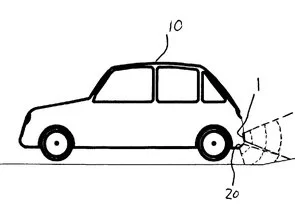
This first version is connected to the chassis of the car, to 12V of the reversing spot and to the aluminum strip that acts as a sensor. It must be placed at a height of about 50 cm from the floor, behind the plastic bumper.
In my case, the detection range is from about 70cm, more than enough for the application.
Clarification: This proves it and it works by detecting people. I also detect objects like a chair, or metal. I still have to prove what happens with cars, in real situations (it should work without problems, a car is much bigger and more massive than me) and probably make improvements in the program.
Any suggestion, question or idea is more than welcome. The circuit is VERY simple to make, what is somewhat difficult is to build the right sensor. Do not give up, it works.
When I have a little more time, I will post some photos and maybe a video.
PARKING SENSOR CIRCUIT WITH PIC12F675 TEST
With the same method used in different microcontroller has two circuits used in both series one microchip pic 12f675 circuits belonging to the other with the 16F628 was performed with software written in the C language, diagrams and drawings have PCBs.
Source: PARKING SENSOR CIRCUITS PIC12F675
Alternative Source: http://www.forosdeelectronica.com/ alternative link Parking sensor circuits project files: without-use-ultrasonic-sensors-parking-sensor-circuits-pic12f675.RAR
- What sensing method does this parking sensor use?
It uses a capaciflector capacitive proximity sensing method rather than ultrasonic sensing. - Which microcontroller is used in the design?
The design uses a PIC12F675; PICs with a T1CKI input such as 16F628 can also be used. - How is the sensor physically constructed?
An adhesive aluminum tape strip is applied over an insulating PVC strip along the bumper, forming the sensor plate while the car body acts as the other capacitor plate. - How does the circuit indicate distance?
The oscillator frequency changes with proximity; the PIC measures pulses and outputs three beep patterns for near, middle, and far distances. - Do I need to connect the SHIELD terminal?
The schematic includes a SHIELD terminal, but the author recommends initial tests without connecting SHIELD because it reduced sensitivity in their case. - What files are provided with the project?
Provided files include JPG schematic, Livewire schematic, PCB in PCB Wizard format, capaciflector patent PDF, original oscillator image, PIC HEX and CCS C source code. - Can I add visual distance indication?
Yes, CLOCK and DATA outputs are available to connect a 4094 shift register and LEDs to create a bar indicating approximate distance. - What power and mounting does the system require?
The prototype connects to the car chassis ground, the 12V reversing light power, and the aluminum strip sensor mounted about 50 cm above the ground behind the bumper. - What detection range was reported?
The author reports a detection range of about 70 cm in their setup. - Does the circuit detect different object types?
The author tested detection of people, chairs, and metal objects; vehicle detection was not fully tested but expected to work.