WEBSD
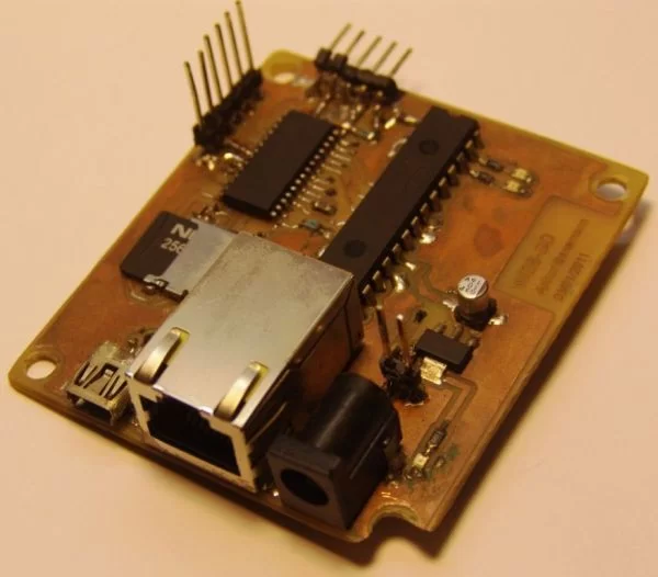
This is a development board for the PIC24F series of microchip, with:
- USB ( plug it to any computer)
- Ethernet ( plug it to the internet)
- SD card ( save and read all data you will need)
I developed this thing as a learning platform, it worked ( still is). So if you always want to go a step further in microcontrollers as i want, it’s a nice way of doing it . The problem i had is that microchip examples are for their development board, which i don’t have access. So i developed my one board and examples, and i saved all the steps so it would be easier to someone to get started.Going from a simple ping to a webpage with ajax.
Just to give a head start see some of the things i have done so far with this board:
- An Touch keyboard, usable as a standard USB keyboard.
- A Video Game ( pong and snake games) , with TV output, and connection to a PC Keyboard ( the old PS/2 ) for control.
- Picture frame, reads pictures form the SD card and show them on the TV.
- Controling a 5 volt LCD and some leds, with just 3 wires ( the MCU is 3.3V)
- Web server, where you can see some status of the board as temperature, the position of a Pot and a Button, control some leds and the LCD ( all this from the internet)
And the things i know before i started ( just a checklist):
- the right side of a soldering iron
- program in c ( just the basics)
- programing PICs in assembler ( I’ve been stuck here for a long time, but it isn’t needed)
- how to make a PCB
- a little bit electronics
- debugging
It all started when i saw this project:
web-server-on-a-business-card-part-2 ( thank you HACKADAY)
The idea of controlling something trought the internet was really nice, so i bought the chip. But when i was delivered classes started. One Year later, i started to read a promising book:
Programming 16-Bit PIC Microcontrollers in C: Learning to Fly the PIC 24
I was the 24F, i started right away. Breadboard, wire-mess, and the first programs were running. But as i advanced in the book i felt the need for a PCB. Hackaday project was my base, but i wanted i little bit more. An USB connector, and some pins fore expansions.The WEBSD board was born.
After I developed some extra boards to plug. If i want to do a new thing with the board, just design a simple expansion board.
Follow the next pages to see more about the project. Project files are annexed on this page.
Main Board
Jump this if you have no interest on the design part of the project.
The main board was been based on the hackaday project. It’s name come from the two main thing on it:
- WEB – Internet connection
- SD – The memory card
I was one of my first projects with a PIC24F, and the power of this chips and C combined scared me.
Layout was easy because of the PPS (Peripheral Pin Select) feature of this family. I allows the I/O of the digital peripheral to be assigned to almost any pins. But i was low on the pin count, but squeezed 4 pins out of it for expansions.
Power is done by a small power supply rated for 5v 500mA ( a standart 7805 PS). I do not chose USB power because of the current draw by the Ethernet chip.
To put all the connectors on one side , and to keep a small size, a double layer board was needed. i got addicted by smd parts, they can be faster to solder, and there is no need to drill so many holes in the board. Unfortunately i didn’t bought the Smd version of the ENC28j60 so it is a DIP part.
The MCU choice was simple, i wanted to learn to use the 24F family, USB was a nice feature to explore, SOIC package (QFN packages still frightens me). So i just pick the one with the biggest program memory.
The ICSP programming connector is for the pickit2 footprint, i is used also as a rs232 serial port. You can see the communications using the terminal provided with the pickit2 or with a external serial port ( allows for more speed)
Part-list ( with mouser reference) :
| Qty | Value | Device | Parts |
| 3 | red | LEDCHIPLED_0805 | LED1, LED2, LED3 |
| 8 | 0.1uF | C-EUC0805 | C2, C4, C6, C7, C9, C10, C11, C12 |
| 2 | 1uF | C-EUC0805 | C5, C8 |
| 1 | 2K32 | R-EU_R0805 | R12 |
| 2 | 10k | R-EU_R0805 | R1, R5 |
| 1 | 10uF | CPOL-EU153CLV-0405 | C3 |
| 1 | 25Mhz | CRYSTALHC49UP | Q2 |
| 2 | 22pf | C-EUC0805 | C15, C16 |
| 4 | 49R9 1% | R-EU_R0805 | R8, R9, R10, R11 |
| 1 | 60ohms | I_0805 | L1 |
| 1 | 330R | R-EU_R0805 | R4 |
| 2 | 330R | R-EU_R0805 | R2, R3 |
| 1 | AP1117E33 | V_REG_LM1117SOT223 | IC1 |
| 1 | ENC28J60-DIL | ENC28J60-DIL | IC2 |
| 1 | J1006LONG | Ethernet Connector | RJ1 |
| 1 | PIC24FJXXGB002 | PIC24FJXXGB002 | U$1 |
| 1 | SD | SD | U$2 |
| 1 | USB-MB | USB-MB | U$4 |
| 1 | power jack | JACK-PLUG1 | J2 |
TempLedPotButton Board
Jump this if you have no interest on the design part of the project.
The first expansion board i designed, as simple as it can be.
I has exactly what the name says:
- Temp – Temperature sensor, one LM35 power from the 5v supply , which gives 10mV/°C.
- Led – no mystery here, a led an a resistor
- Pot – Potentiometer connected as a voltage divider, just waiting to be read by the ADC
- Button – a pushbutton to the ground, no pull-ups are used as the PIC already has them.
I have i problem here in Brasil, it’s hard to get parts. I have to buy from the USA ( paying a lot of taxes , up to 200%) just to get a couple of “female headers“. So i know that the connectors i used are made for cables. Nice headers would be much better (like those in the arduino).
I was experimenting with my board manufacturer capabilities, so fell free to increase the size of those tracks ( 8mil tracks are hard with the toner transfer method).
Touch DirectKey Board
I had already written a routine for touch sensing in assembler for the PIC16, but the 24Fs has another nice feature the Charge Time Measurement Unit (CTMU). Using it as a current source it’s a lot easy to measure capacitance.
So a simple explanation of the touch sensors: when you put your finger close to the big square on the board you increase the parasitic capacitance of that track. The micro continually monitor the line for changes on the line detecting a button press.
No big things on this board, just a piece of acrylic on the top to simulate the front panel of something ( i broke one corner when i was cutting). I made a simple silk screen on the board to identify the buttons. For a better performance the tracks must be as close as possible to the finger, but i put them on the bottom side of the board because if i can make it work like this, it will work well when used normally.
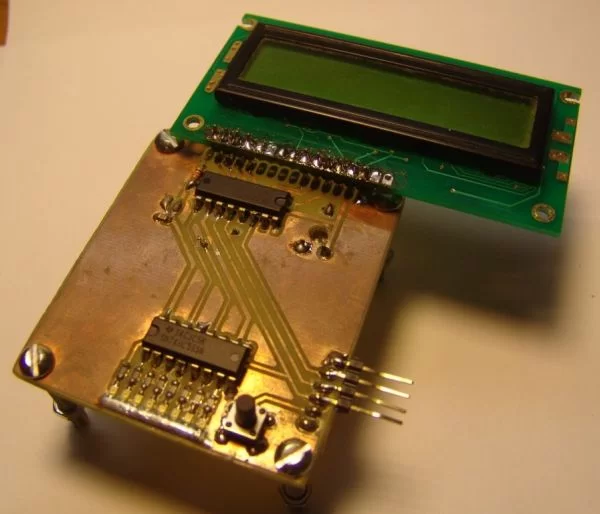
LCDSerial
Jump this if you have no interest on the design part of the project.
No development board would be complete without a LCD.But there is a big problem here, in fact two:
- The power for this PIC is 3.3V, and all alphanumeric LCD i have at hand are only 5v. There is the possibility for connecting 5V inputs to some of the pins on the micro, but i had use all of them. ( if you take out the USB pins there isn’t enough pins left)
- Even if it was a 5V part, i had only left 4 expansion pins, the lcd needs at least 6 ( nimble, only write mode)
So i looked around until i find the solution on a PICLIST post, i little more and i found this. One 74HCT595chip would do the job of the level conversion. I think it would be better explained by “dangerous prototypes”, so take a look over there.
But why stop on a LCD if you are using a shift register? Lets put some Leds on this thing. Another ‘595 in series and we are good to go.
The hidden position of the contrast potentiometer is worth mention. i projected with a lcd, but soldered other so it stayed in the wrong position.
Part-list (with mouser reference):
| Qty | Value | Device | Parts |
| 8 | LEDCHIP-LED0805 | LED1, LED2, LED3, LED4, LED5, LED6, LED7, LED8 | |
| 1 | TAC_SWITCH | S1 | |
| 1 | 0.1uF | C-EUC0805 | C1 |
| 1 | 1K | R-EU_0204/5 | R2 |
| 1 | 10K | TRIM_EU-LI10 | R1 |
| 2 | 74HC595N | 74HC595N | IC1, IC2 |
| 8 | 330R 0805 | R-EU_R0805 | R3, R4, R5, R6, R7, R8, R9, R10 |
| 1 | HD44780-LCD | HD44780-LCD | LCD1 |


