


Summary of PIC Controlled Relay Driver using PIC16F84A
This project is a PIC16F84A-based relay driver board that controls four separate 12V SPDT relays to switch heaters, lamps, computers, or motors. The design emphasizes robust AC supply protection using a 1:1 line filter transformer, varistor, fuse, and multiple capacitors and regulators to minimize line noise and provide reliable power for industrial use.Parts used in the PIC Controlled Relay Driver:
- PIC16F84A Microcontroller
- 220V/12V 3.6VA (or 3.2VA) PCB Type Transformer (EI 38/13.6)
- Line Filter (2×10mH 1:1 Transformer)
- 4 × 12V Relay (SPDT Type)
- 4 × BC141 NPN Transistor
- 5 × 2 Terminal PCB Terminal Block
- 4 × 1N4007 Diode
- 250V Varistor (20mm Diameter)
- PCB Fuse Holder
- 400mA Fuse (250V)
- 2 × 100nF/630V Unpolarized Capacitor
- 220uF/25V Electrolytic Capacitor
- 47uF/16V Electrolytic Capacitor
- 10uF/16V Electrolytic Capacitor
- 2 × 330nF/63V Unpolarized Capacitor
- 100nF/63V Unpolarized Capacitor
- 4MHz Crystal Oscillator
- 2 × 22pF Capacitor
- 18 Pin 2 Way IC Socket
- 4 × 820 Ohm 1/4W Resistor
- 1 × 1K 1/4W Resistor
- 1 × 4.7K 1/4W Resistor
- 7805 Voltage Regulator (TO220)
- 7812 Voltage Regulator (TO220)
- 1A Bridge Diode
Project Summary
This circuit is a relay driver that is based on a PIC16F84A microcontroller. The board includes four relays so this lets us to control four distinct electrical devices. The controlled device may be a heater, a lamp, a computer or a motor. To use this board in the industrial area, the supply part is designed more attentively. To minimise the effects of the ac line noises, a 1:1 line filter transformer is used.
Project Description
The components are listed below.
1 x PIC16F84A Microcontroller
1 × 220V/12V 3.6VA (or 3.2VA) PCB Type Transformer (EI 38/13.6)
1 x Line Filter (2×10mH 1:1 Transformer)
4 × 12V Relay (SPDT Type)
4 x BC141 NPN Transistor
5 × 2 Terminal PCB Terminal Block
4 × 1N4007 Diode
1 × 250V Varistor (20mm Diameter)
1 x PCB Fuse Holder
1 × 400mA Fuse
2 × 100nF/630V Unpolarized Capacitor
1 × 220uF/25V Electrolytic Capacitor
1 × 47uF/16V Electrolytic Capacitor
1 × 10uF/16V Electrolytic Capacitor
2 × 330nF/63V Unpolarized Capacitor
1 × 100nF/63V Unpolarized Capacitor
1 × 4MHz Crystal Oscillator
2 × 22pF Capacitor
1 × 18 Pin 2 Way IC Socket
4 × 820 Ohm 1/4W Resistor
1 × 1K 1/4W Resistor
1 × 4.7K 1/4W Resistor
1 × 7805 Voltage Regulator (TO220)
1 × 7812 Voltage Regulator (TO220)
1 × 1A Bridge Diode
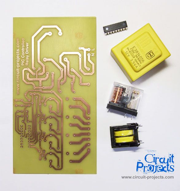
The transformer is a 220V to 12V, 50Hz and 3.6VA PCB type transformer. The model seen in the photo is HRDiemen E3814056. Since it is encapsulated, the transformer is isolated from the external effects.
{mosgoogle}A 250V 400mA glass fuse is used to protect the circuit from damage due to excessive current.
A high power device which is connected to the same line may form unwanted high amplitude signals while turning on and off. To bypass this signal effects, a variable resistor (varistor) which has a 20mm diameter is paralelly connected to the input.
Another protective component on the AC line is the line filter. It minimises the noise of the line too. The connection type determines the common or differential mode filtering.
The last components in the filtering part are the unpolarized 100nF 630V capacitors. When the frequency increases, the capacitive reactance (Xc) of the capacitor decreases so it has a important role in reducing the high frequency noise effects. To increase the performance, one is connected to the input and the other one is connected to the output of the filtering part.
For more detail: PIC Controlled Relay Driver using PIC16F84A
- What microcontroller is used in the project?
The project uses a PIC16F84A microcontroller. - How many relays does the board include?
The board includes four 12V SPDT relays. - What is used to minimize AC line noise?
A 1:1 line filter transformer, varistor, and unpolarized capacitors are used to minimize AC line noise. - What protects the circuit from excessive current?
A 250V 400mA glass fuse in a PCB fuse holder protects the circuit from excessive current. - What transformer specifications are used for power supply?
A 220V to 12V, 50Hz, 3.6VA (or 3.2VA) PCB type transformer is used. - What component is used to bypass high-amplitude switching transients?
A 20mm diameter varistor is connected in parallel on the input to bypass switching transients. - Which voltage regulators are included on the board?
The board includes a 7805 and a 7812 voltage regulator (both TO220). - Why are unpolarized 100nF 630V capacitors used?
They reduce high frequency noise because their capacitive reactance decreases as frequency increases; one is placed on the input and one on the output of the filtering part.
Related projects
PIC Stepper Motor Controller using PIC16F84A with Proteus Simulation
Introduction Stepper motors are widely used in embedded systems and DIY electronics projects where precise position control is required. This PIC Stepper...
Programmers & ICSP · PIC16F84APIC Musical Doorbell using PIC16F84A with Proteus Simulation
IntroductionThis microcontroller project demonstrates a musical doorbell built around a PIC16F84A and a simple piezo sounder.Using two push buttons, the system allows...
Beginner Tutorials · PIC16C84Exploring the World of PIC Microcontrollers: An Architectural Overview
A Peripheral Interface Microcontroller (PIC), developed by General Instruments Microcontrollers in 1993, operates under software control and is programmed to execute various...
Development Boards & Kits · PIC18F4520Voltage Measurement with A PIC Microcontroller
Voltage Measurement with PIC Microcontroller articulates a methodical framework for facilitating analog voltage measurement using the PIC18F4520, an advanced member of Microchip’s...
Development Boards & KitsUltra-Low Power: Microcontroller Standby Current to 130uA with OPEnS Power Control Board
At the OPEnS Lab, a key focus for our projects is achieving exceptionally long battery life. This was particularly true for the...
Development Boards & KitsAn Integrated Approach to Developing Applications with Microchip PIC Microcontrollers
1. Introduction In our daily lives, a variety of devices such as telephones, household appliances, and cars incorporate "smart" electronics, typically manifested...

Ibrar Ayyub
I am an experienced technical writer holding a Master's degree in computer science from BZU Multan, Pakistan University. With a background spanning various industries, particularly in home automation and engineering, I have honed my skills in crafting clear and concise content. Proficient in leveraging infographics and diagrams, I strive to simplify complex concepts for readers. My strength lies in thorough...