Summary of MULTI-FUNCTIONAL PICMICRO DEVELOPMENT BOARD (BREADBOARD SUPPORTED)
This article describes a multifunctional PICmicro development board (breadboard supported) for testing and project development with shared resources, C test program (pic_board_test.c), and PCB/breadboard-ready circuit. It supports multiple PIC18 devices, provides numerous I/O, peripheral interfaces, display options, communication ports, and power circuitry for 9–12 V adapters.
Parts used in the Multi-functional PICmicro Development Board:
- 40-pin socket (for PIC18F442/452/448/458/4550)
- 28-pin socket (for PIC18F242/252/248/258)
- Female header pins (accessible to all ports)
- DIP switches (peripheral switching)
- LCD connectors (two different connections)
- 4 x 7-segment displays
- HEF4511 driver IC (for 7-segment multiplexing)
- 2 x 8 LEDs (LED arrays)
- Potentiometer (analog simulation)
- Reset button
- 4 push buttons
- I2C interface (for 24C04 EEPROM)
- 2 x RS232 interfaces
- SUB-D socket (one) and RS232 pin header
- Breadboard (640 holes)
- ICSP header
- ICD connection header
- On-board power circuit (7805 regulator)
- DC power jack for 9V or 12V adapter
- PCB and schematic files (project resources and test program pic_board_test.c)
quite an advanced picmicro trial, testing, project development cycle a lot of functions all resources shared also the circuit for testing c language prepared test program at (pıc_board_test.c) had the most excellent on the…Electronics Projects, Multi-functional PICmicro Development Board (Breadboard Supported) “avr development board, pic development board, ”
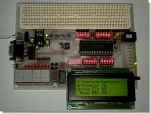
quite an advanced picmicro trial, testing, project development cycle a lot of functions all resources shared also the circuit for testing c language prepared test program at (pıc_board_test.c) had the most excellent on the PCB Breadboard for the installation department leave have pic development circuit 7805 with a volt supply voltage dc 12v or 9v adapter leveling feature can run with
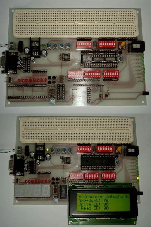
PICMICRO DEVELOPMENT BOARD FEATURES
- 40 pin socket for example PIC18F442/452 PIC18F448/458 or or PIC18F4550
- 28 pin socket for example PIC18F242/252 PIC18F248/258 or
- accessible to all ports via Headers (females)
- Peripheral switchable with DIP switches
- two different LCD Connections
- 4 x 7-segment displays (with IC HEF4511 multiplexed)
- 2 x 8 LED’s
- 1 Potentiometer for analog simulation
- 1 Reset button to reset module
- 4 buttons
- I2C, etc. for 24C04
- 2 x RS232 with 1 x SUB-D socket (2 on pin header)
- Breadboard with 640 holes
- ICSP and ICD connection
- Power on Board
- Dimensions: 190mm x 140mm
PICMICRO DEVELOPMENT BOARD
source: hanf-elektrotechnik.de/ Multi-functional PICmicro Development Board schematic pcb files alternative link: multi-functional-picmicro-development-board.rar alternative link2 alternative link3
- What PIC microcontrollers does the board support?
The board supports PIC18F442/452/448/458/4550 in the 40-pin socket and PIC18F242/252/248/258 in the 28-pin socket. - Can I access all PIC ports on the board?
Yes, all ports are accessible via female header pins. - Does the board include display options?
Yes, it includes two LCD connections and four 7-segment displays driven by HEF4511. - How is peripheral selection handled?
Peripherals are switchable using DIP switches. - Is there provision for EEPROM interfacing?
Yes, there is an I2C interface for a 24C04 EEPROM. - Does the board provide serial communication ports?
Yes, it provides two RS232 interfaces with one SUB-D socket and a pin header for the other. - Can I use the board for prototyping on a breadboard?
Yes, it includes a 640-hole breadboard for prototyping. - Is in-circuit programming and debugging supported?
Yes, the board includes ICSP and ICD connection headers. - What power supply does the board require?
The on-board power uses a 7805 regulator and can run from a 9V or 12V DC adapter. - Are circuit files and test programs available?
Yes, schematic, PCB files, and a prepared C test program (pic_board_test.c) are shared with the project resources.