
Summary of LED PIXELS PIC24FJ64GA004 DYNAMIC TILE DISPLAY
This article describes a dynamic tile display project using 2-inch square 8x8 LED matrices with red and green LEDs. Each tile is controlled by a PIC24FJ64GA004 microcontroller, utilizing a ULN2803 for current drive and a MAX756 boost regulator for power management. The system features wireless synchronization via spring-loaded connectors and supports animated downloads based on unique tile IDs.
Parts used in the Dynamic Tile Display:
- 2” square 8×8 LED displays
- PIC24FJ64GA004 MCU
- ULN2803 Darlington transistor array
- MAX756 boost regulator
- Two AAA batteries (NiMH)
- External crystal oscillator (7.3728MHz)
- Spring loaded connectors
The tiles are based on 2” square 8×8 LED displays. Each pixel in the display has a red and green LED. The LEDs are arranged in a matrix, with the red and green LEDs... Electronics Projects, LED pixels PIC24FJ64GA004 Dynamic Tile Display “microchip projects, microcontroller projects, “
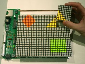
The tiles are based on 2” square 8×8 LED displays. Each pixel in the display has a red and green LED. The LEDs are arranged in a matrix, with the red and green LEDs sharing a common cathode tied to the columns of the matrix, and individual connections for the red and green along the rows of the matrix. The matrix has 24 connections (8 columns, 8 red rows & 8 green rows).
Underneath each display, a PIC24FJ64GA004 MCU drives the LEDs. This MCU has 35 I/O pins, 24 are used for directly driving the display. Since the MCU can’t quite sink enough current if all of the LEDs in a column are on, the column lines are connected through a ULN2803 Darlington transistor array to provide the necessary current drive.
Because of the matrix configuration, only one column of the display is lit at a time. The MCU scans the columns at about 1000Hz to provide the appearance of a steady display. Because the LEDs have a 1/8th duty cycle, no current limiting resistors are needed
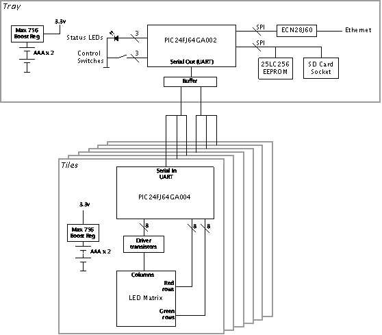
Power for each tile is supplied by two AAA batteries, which is fed through a MAX 756 boost regulator to get the 3.3V required. The rechargeable NiMH AAAs have about 800mAh. Each tile draws about 100-280 mA depending on the number of illuminated LEDs. The boost regulator is about 80% efficient, giving an overall battery life of around six hours.
Since accurate timing is a requirement of the design, an external crystal oscillator is provided for the MCU. It uses the same 7.3728MHz design as the Microchip 28-Pin demonstration board.
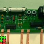
At the bottoms of each tile, spring loaded connectors make contact with signal connections in the tray. The tile listens for these signals to download and synchronize animations.
The firmware on the tiles is completely interrupt driven. Two timers control the display, the first (at about 1000Hz) takes care of scanning the columns of the display in its ISR. The second switches from frame to frame at a rate controlled by the animation downloaded into the tile.
Another ISR executes when a character is received via the UART’s serial input. This allows the tile to execute a number of commands, such as display a test image or an ID number, or download an animation sequence. Each tile has a unique ID number. When the tray broadcasts animation data, the tile checks the ID number of the broadcast. If it matches, the tile loads the animation into its RAM, otherwise it ignores it. A red “pinwheel” animation displays while the tile is downloading an animation, this switches to green when the download is complete. Author: John Peterson
Source: LED PIXELS PIC24FJ64GA004 DYNAMIC TILE DISPLAY files: led-pixels-pic24fj64ga004-dynamic-tile-display.RAR alternative link2 alternative link3
-
How are the red and green LEDs arranged in the matrix?
The red and green LEDs share a common cathode tied to the columns of the matrix, while having individual connections along the rows. -
Why is a ULN2803 used in this project?
The ULN2803 Darlington transistor array is used because the MCU cannot sink enough current if all LEDs in a column are on simultaneously. -
Does the design require current limiting resistors?
No, current limiting resistors are not needed because the LEDs have a 1/8th duty cycle due to the scanning method. -
What is the expected battery life for each tile?
The overall battery life is around six hours, provided by two rechargeable NiMH AAA batteries with about 800mAh capacity. -
How does the MCU synchronize animations with other tiles?
The tile listens for signals via spring loaded connectors, checks the broadcast ID number against its own unique ID, and loads the animation if they match. -
What frequency is used to scan the display columns?
The MCU scans the columns at about 1000Hz to provide the appearance of a steady display. -
How can you tell if an animation download is complete?
A red pinwheel animation displays during the download, which switches to green when the download is complete.
