Summary of DSPIC30F2010 PWM MOTOR DRIVER CIRCUIT DRV8402
The article describes a motor driver circuit centered on the dsPIC30F2010 microcontroller and the DRV8402 dual H-bridge driver. The system generates PWM signals to control conventional DC, brushless DC, and 3-phase synchronous motors with permanent magnets. It features serial communication for PC connection, an A/D converter for accurate measurements, and requires a specific crystal oscillator setup to achieve 30 MIPs processing speed.
Parts used in the DRV8402 Motor Driver Circuit:
- dsPIC30F2010 microcontroller
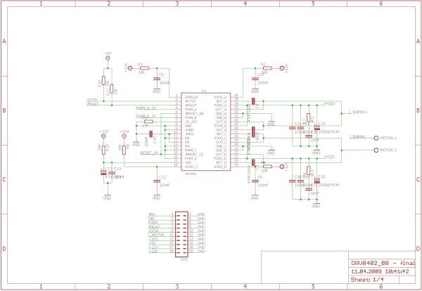
- DRV8402 double full H-bridge driver
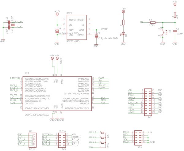
- Crystal oscillator (7.3728 MHz)
- Two capacitors for the crystal input
- A/D converter
- Reference voltage source
- Serial communication module
- MOSFET transistors (integrated in DRV8402)
DRV8402 Motor Driver Circuit The main component is the microcontroller dsPIC30F2010, who for its activities needs outside of the power supply voltage also a source of accurate clock pulses. In order to achieve the… Electronics Projects, dsPIC30F2010 PWM Motor Driver Circuit DRV8402 “dspic projects, microchip projects, microcontroller projects, motor control circuit, motor driver circuit, pwm circuits, “
DRV8402 Motor Driver Circuit The main component is the microcontroller dsPIC30F2010, who for its activities needs outside of the power supply voltage also a source of accurate clock pulses. In order to achieve the speed of 30 MIPs, we had to calculate the speed of the desired crystal. Each instruction takes four bars of the hourly pulse and when using the multipliers impulses 16x PLL we get a crystal about the size of 7,3728 MHz. According to the datasheet of the processor is needed to connect to the input of the crystal two capacitors.
DSPIC30F2010 MOTOR CONTROL CIRCUIT SCHEMATIC
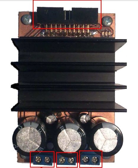
DRV8402 is a very powerful double full H-bridge with integrated MOSFET transistors. Their internal resistance RDS(on) has a low value of 80 m at a temperature of 25 °C…. Each of the jumper is composed of two puls each separate country. It can be every half of the power the different levels of the supply voltage. And when the power supply voltage to 50V. Current the load of each bridge is 5 And continuous at peak times up to 12 a And at parallel involvement of both bridges can be controlled the flow 10 And in the peak loads in 24 And. This circuit allows the management of conventional and brushless dc motors and control 3-phase synchronous motors with permanent magnets. For the management of the engines are on circuit inputs a PWM signal, which may be in the range from 25 KHz to 500 KHz at high efficiency and good control.
DRV8402 SCHEMATIC DUAL FULL BRIDGE PWM MOTOR DRIVER
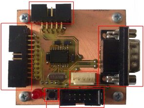
For a hardware implementation of the procedure we designed two modules. The first module is folded from the microcontroller DSPIC30F2010 and auxiliary circuits required to obtain the desired position and the resulting control PWM signal. Further has serial communications for connection to a PC and own a source of reference voltage for accurate measurement of quantities from the a/D converter.
source: DSPIC30F2010 PWM MOTOR DRIVER CIRCUIT DRV8402 pwm motor dirver circuit pcb schematic all files alternative links: dspic30f2010-pwm-motor-driver-circuit-drv8402.rar alternative link2
- What is the main component of this motor driver circuit?
The main component is the microcontroller dsPIC30F2010. - How can the speed of 30 MIPs be achieved?
It is achieved by using a 7.3728 MHz crystal with 16x PLL multipliers. - Does the DRV8402 support different supply voltages?
Yes, each half of the power can have different levels of supply voltage up to 50V. - What is the continuous current rating for each bridge?
The load current for each bridge is 5 Amperes continuously. - Can this circuit control brushless DC motors?
Yes, the circuit allows management of conventional and brushless DC motors. - What is the frequency range for the PWM signal inputs?
The PWM signal may be in the range from 25 KHz to 500 KHz. - Why are two capacitors connected to the crystal input?
The processor datasheet requires connecting two capacitors to the crystal input. - What type of communication does the hardware implementation include?
The design includes serial communications for connection to a PC.