
Summary of Building the Inchworm ICD2 PIC Programmer / Debugger using PIC16F877
This article guides users through assembling the Inchworm, an ICD2 clone programmer and debugger compatible with MPLAB. It emphasizes washing the PCB before assembly and soldering low-profile components first. The guide details installing specific resistors (5% tan and 1% blue) and diodes, stressing correct orientation based on cathode bands. A battery-powered variant uses Schottky diodes instead of standard ones.
Parts used in the Inchworm ICD2 PIC Programmer / Debugger:
- Circuit board
- Mild detergent
- Low profile parts
- Tan 5% tolerance resistors
- Blue 1% metal film resistors
- Small glass diodes (1N4148 or 1N914)
- Larger power diodes (1N5817 Schottky or 1N4001)
- Battery for power
Building the Inchworm ICD2 PIC Programmer / Debugger
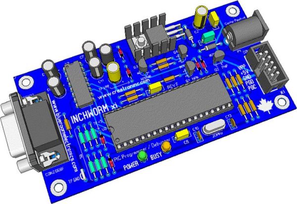
This instructable is an illustrated walk through building an ICD2 clone called the Inchworm.
It’s a straight forward kit that lets you build an MPLAB ICD2 compatible Programmer and Debugger.
There are lots of Programmers out there but very few include a debugger, (A debugger lets you single step through your program and set watch lists (see your variables) and much more).
The full manual including schematic and notes can be found at blueroomelectronics
Preparing the PCB
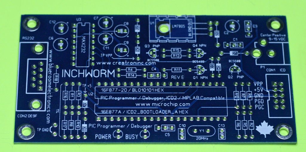
Solder all the “low profile” parts
Here I’ve soldered and trimmed the leads of all the low profile parts. When building a PCB it’s often easiest to assemble the small parts first. This method gives you more room to work when adding the taller parts.
Add the resistors first, noting the tan resistors are the common 5% tolerance versions and the blue resistors are 1% metal film types.
Now install the diodes, both the smaller glass diodes and the larger power diodes require you to pay attention to the colored band on the cathode of all diodes. Failure to install the diodes in the correct orientation will keep the Inchworm or any electronic project from functioning properly.
Note: I’m building a battery powered version for demos, the power diodes I used are low dropout Schottky 1N5817 types instead of the more common 1N4001 diodes. The six small glass diodes are common 1N4148 types (you can also use 1N914)
- What is the Inchworm?
It is a kit that builds an MPLAB ICD2 compatible Programmer and Debugger. - How should the circuit board be prepared?
Wash it in mild detergent and thoroughly dry before assembly. - Which parts should be assembled first?
Assemble the small low profile parts first to leave room for taller components. - What distinguishes the two resistor types mentioned?
Tan resistors are 5% tolerance while blue resistors are 1% metal film types. - Why is diode orientation critical?
Installing diodes incorrectly will prevent the project from functioning properly. - What diodes are used for a battery powered version?
Low dropout Schottky 1N5817 types are used instead of common 1N4001 diodes.
