


Summary of STEPPER MOTOR CONTROL CIRCUIT WITH PIC16F84A MOSFET
This article describes a PIC16F84A-based stepper motor control circuit using MOSFETs. It features two buttons for directional control (left/right) and a stop button to halt the motor. Speed is adjustable via an RC oscillator or by modifying resistor R, with an option to add a potentiometer. The project includes Proteus simulation files and source code available for download.Parts used in the Stepper Motor Control Circuit:
- PIC16F84A microcontroller
- MOSFETs
- Stepper motor
- Left button
- Right button
- Stop button
- Frequency crystal oscillator
- RC oscillator
- Resistor R
- Potentiometer (optional)
PIC16F84 stepper motor control circuit is the button to the right to the left button is pressed, the motor rotates continuously in the opposite direction to the right Doderer stop button will stop the motor. The engine speed is... Electronics Projects, Stepper Motor Control Circuit with PIC16F84A mosfet "microchip projects, microcontroller projects, pic assembly example, pic16f84 projects,
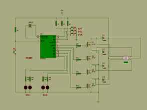
PIC16F84 stepper motor control circuit is the button to the right to the left button is pressed, the motor rotates continuously in the opposite direction to the right Doderer stop button will stop the motor.
The engine speed is adjusted by changing the setting of a frequency crystal oscillator RC oscillator instead of the value of resistor R is connected and changing the speed setting that can be added to potl
STEPPER MOTOR DRIVER CIRCUIT DIAGRAM
Stepper Motor Control Circuit proteus simulation pic assembly source code files:
FILE DOWNLOAD LINK LIST (in TXT format): LINKS-88.zip
Source: STEPPER MOTOR CONTROL CIRCUIT WITH PIC16F84A MOSFET
Quick Solutions to Questions related to Stepper Motor Control Circuit:
- How does the left button affect the motor?
Pressing the left button causes the motor to rotate continuously in one direction. - What happens when the right button is pressed?
The motor rotates continuously in the opposite direction when the right button is pressed. - How can I stop the motor?
Pressing the stop button will stop the motor. - Can the engine speed be adjusted?
Yes, the speed is adjusted by changing the frequency crystal oscillator or the value of resistor R. - Is it possible to add a potentiometer for speed control?
Yes, a potentiometer can be added to change the speed setting. - What type of driver circuit is used in this project?
A MOSFET stepper motor driver circuit is used. - Where can I find the source code?
Source code files are available in the FILE DOWNLOAD LINK LIST in TXT format. - Does the project include Proteus simulation files?
Yes, the project includes stepper motor control circuit Proteus simulation files.
Related projects
PIC Stepper Motor Controller using PIC16F84A with Proteus Simulation
Introduction Stepper motors are widely used in embedded systems and DIY electronics projects where precise position control is required. This PIC Stepper...
Programmers & ICSP · PIC16F84APIC Musical Doorbell using PIC16F84A with Proteus Simulation
IntroductionThis microcontroller project demonstrates a musical doorbell built around a PIC16F84A and a simple piezo sounder.Using two push buttons, the system allows...
Beginner Tutorials · PIC16C84Exploring the World of PIC Microcontrollers: An Architectural Overview
A Peripheral Interface Microcontroller (PIC), developed by General Instruments Microcontrollers in 1993, operates under software control and is programmed to execute various...
Motors & RoboticsReal-Time CAN-Based Vehicle Monitoring System with PIC MCU
INTRODUCTION The Controller Area Network (CAN) is a robust vehicle communication bus standard that was primarily developed for automobile applications but has...
Motors & RoboticsEasy Way to Learn Robotics Using Microcontrollers: A Beginner’s Guide
The title, "Easy Way to Learn Robotics Using Microcontrollers," promises an accessible entry point for those curious about the exciting world of...
Motors & Robotics · PIC16F877AEfficient Sun-Following Robot: A Solar Tracker with Microcontroller Control
Abstract The impending global challenge of dwindling non-renewable fuel resources underscores the urgency of transitioning towards renewable energy alternatives like solar power....

Muhammad Bilal
I am a highly skilled and motivated individual with a Master's degree in Computer Science. I have extensive experience in technical writing and a deep understanding of SEO practices.