Summary of PICMicro Project using PIC16F84 Microcontroller
This article introduces a beginner-friendly PICMicro application using the 16F84 microcontroller. The circuit features two LEDs and a pushbutton, designed to demonstrate basic input/output operations. It emphasizes using a breadboard for prototyping, a ceramic resonator for clocking, and internal pull-up resistors to simplify the design. The guide also highlights practical layout tips, such as ensuring easy chip removal from sockets.
Parts used in the PICMicro Project using PIC16F84 Microcontroller:
- 4.7K 0.25 Watt Resistor
- 220 Ohm 0.25 Watt Resistor
- 10 uF 25 Volt Electrolytic Capacitor
- 0.1 uF 16 Volt Tantalum Capacitor
- 78L05 Voltage Regulator
- PIC16F84 Microcontroller
- 5 mm Red LEDs
- "Momentary On" SPST Pushbutton
- Prototype Card
- Wiring
- Power Supply (> 6 Volts if Voltage Regulator used)
- 4MHz Ceramic Resonator (With Internal Capacitors)
In the past two weeks, I discussed the prerequisits for starting your first application and the issues surrounding PICMicro programmers and what to look for. With this background, I am now ready to present what I think is a good first application for somebody learning about the PICMicro. This circuit is not as simple as what I started with in “Programming and Customizing the PIC Microcontroller”, but can be used in the same way to experiment with different ideas and trying out new concepts.
The application itself consists of the 16F84 PICMicro (with power, reset and clocking “core”) with two LEDs and a button. One of the LEDs is lit by the PICMicro while the other is lit when the button is pressed.
|
Bill of Materials |
|
| Part Number R1 R2-R3 C1 C2 U1 U2 CR1-CR2 SW1 — — — Y1 |
Value/Comments 4.7K 0.25 Watt Resistor 220 Ohm 0.25 Watt Resistor 10 uF 25 Volt Electrolytic Capacitor 0.1 uF 16 Volt Tantalum Capacitor 78L05 Voltage Regulator PIC16F84 Microcontroller 5 mm Red LEDs “Momentary On” SPST Pushbutton Prototype Card Wiring Power Supply (> 6 Volts if Voltage Regulator used) 4MHz Ceramic Resonator (With Internal Capacitors) |
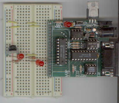
When I built the circuit, I put it on a spring loaded “Breadboard” as is shown at the top of the article. I was able to put on the Voltage regulator at one end of the breadboard with the “red” commoning bar as positive voltage and the blue bar as ground. I used a +12 Volt “Wall Wart” for powering my prototype, but this circuit could be powered by a 9 Volt Alkaline radio battery. As I pointed out in the earlier articles, three “AA” 1.5 Volt Alkaline batteries could be wired in series to provide power as well.
For my prototype, I used a 4 MHz “Ceramic Resonator” for clocking. For this circuit, the operating frequency is not important. If you haven’t used a Ceramic Resonator before, I highly recommend that you look into them because they are a) easier to wire than a crystal and a couple of capacitors and b) are much more robust than a crystal, which means that you will be able to abuse them more and not loose your investment.
The LEDs are lit when the Microcontroller pins that they are connected to are pulled to ground. This is traditional in Microcontroller applications because in most devices, the “0” can “sink” more current than the “1” can “source”. The PICmicro is capable of sourcing enough current to drive an LED, but I prefer using the sink feature because this is the only way that the 8051 can light LEDs directly and this eliminates the need for me to convert mentally how applications work for different devices.
The button connection probably seems unreasonably simple because I have not provided a “pull up” for the switch to pull down. In the interests of keeping the circuit simple, I rely on the internal pull ups in “PORTB” of the PICMicro to provide this function for me. A 4.7K Resistor connected between Vdd and the PICMicro’s I/O pin could also be used if the internal pull ups are not used.
There is one point to make about the layout that you should always keep in mind when developing a circuit with a microcontroller or other programmable device; you should always design the circuit in such a way that the chip can be pulled easily. This means that there should be space at either end for prying the chip up out of its socket or, as I like to do, slide a small screwdriver underneath the PICMicro and “pop” it up simply by twisting it. I know a lot of people that end up cursing themselves because they’ve forgotten to remember this basic operation. In keeping with this theme, when using a “breadboard”, I like to put in a connection between the row of holes above the Microcontroller. This allows me to pull the part without having to figure out where it goes back each time.
For more detail: PICMicro Project using PIC16F84 Microcontroller
- What is the recommended power source for this prototype?
A +12 Volt Wall Wart can be used, or a 9 Volt Alkaline radio battery, or three AA 1.5 Volt Alkaline batteries wired in series. - Why does the author prefer using a Ceramic Resonator over a crystal?
Ceramic Resonators are easier to wire and much more robust than crystals, allowing for more abuse without losing investment. - How are the LEDs lit in this specific circuit design?
The LEDs are lit when the Microcontroller pins connected to them are pulled to ground, utilizing the sink feature of the device. - Does the button connection require an external pull-up resistor?
No, the circuit relies on the internal pull-ups in PORTB of the PICMicro to provide the necessary function. - Can the PICMicro source enough current to drive an LED directly?
Yes, the PICmicro is capable of sourcing enough current to drive an LED, though the author prefers sinking current. - What is a critical layout consideration for the microcontroller chip?
You should always design the circuit with space at either end to allow the chip to be pulled easily out of its socket. - What tool does the author suggest for removing the PICMicro from a socket?
A small screwdriver can be slid underneath the PICMicro and twisted to pop it up simply. - Is the operating frequency important for this specific circuit?
No, for this circuit, the operating frequency is not important.