
Summary of PIC16F876 CONTROL OF 8 SERVOS MOTOR 5 ANALOG CHANNELS I2C BUS
This technical report details a computer control board using the PIC16F876 microcontroller running at 4MHz. The system functions as an I2C slave module capable of controlling eight standard radio control servos and reading five analog inputs via digital conversion. Key features include configurable address selection via dip switches, adjustable servo position, rotation direction, and offset settings. The design simplifies multi-module networking by allowing multiple units on a single bus with minimal overhead, requiring only Ground, SCL, and SDA connections with built-in pullup resistors.
Parts used in the PIC16F876 Servo Motor Control Project:
- PIC16F876 Microcontroller
- I2C Slave Module
- Analog Servos (8 Standard Radio Control)
- Dip Switches
- Pullup Resistors (Integrated)
- Analog Inputs (5 Channels)
Microcontroller PIC16F876 4Mhz Controlled by the I2C slave module and analog servos technical report describes the design, both from the electronic point of view, as a computer control board for I2C bus 8 standard… Electronics Projects, PIC16F876 Control of 8 Servos Motor 5 Analog Channels I2C bus”microchip projects, microcontroller projects, pic assembly example, pic16f876 projects, “
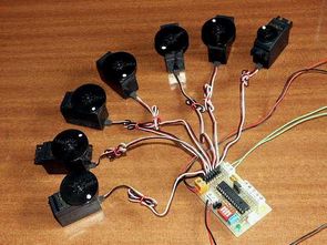
Microcontroller PIC16F876 4Mhz Controlled by the I2C slave module and analog servos technical report describes the design, both from the electronic point of view, as a computer control board for I2C bus 8 standard radio control servos, and 5 analog inputs (analog / digital conversion). The main characteristics of the module are presented as follows:
Acts as Slave by allowing you to select the address dip switches used in the I2C network.
It can be set by both the desired I2C bus position of each servo, as the direction of rotation and the Offset.
Can be read by the I2C bus corresponding to any of the 5 analog inputs of the digital value available (8 bits).
PIC16F876 SERVO MOTOR CONTROL I2C BUS SCHEMATIC

PIC16F876 SERVO TEST
The advantage you get with these modules is precisely the I2C control bus that allows multiple modules such advantage obtained with these modules is precisely the I2C control bus that allows multiple modules of this type connected the same bus. This way they can control lots of servos from a main controller with little overhead in it. Additionally, analog measurement values is very useful for certain types of sensors.
Note: Master and Slave must be connected by three wires: Ground, SCL and SDA. The module presented includes pullup resistors, so it is not necessary to add them.
source : PIC16F876 CONTROL OF 8 SERVOS MOTOR 5 ANALOG CHANNELS I2C BUSPIC16F876 Servo Motor Control pic assembly source code schematic filespic16f876-control-of-8-servos-motor-i2c-bus.rar alternative link2
- How does the module operate within an I2C network?
The module acts as a slave device that allows users to select its specific address using dip switches. - Can the rotation direction of the servos be changed?
Yes, the system can be set to define the desired direction of rotation for each servo. - What is the maximum number of servos this board can control?
The design supports the control of 8 standard radio control servos. - Does the module require external pullup resistors?
No, the module includes pullup resistors, so it is not necessary to add them externally. - How many analog inputs are available for sensor data?
The board provides 5 analog inputs that perform digital value conversion. - What wires are required to connect the Master and Slave?
Master and Slave must be connected by three wires: Ground, SCL, and SDA. - What is the primary advantage of using this I2C control bus?
It allows multiple modules to be connected to the same bus, enabling control of many servos from a main controller with little overhead. - What resolution do the analog input readings use?
The digital values read from the analog inputs are represented as 8 bits.
