
Summary of PIC16F84 RF FISH DETECTOR CIRCUIT
This article describes an RF-based fish detector project using a PIC16F84 microcontroller. A waterproof transmitter attached to a fishing stick detects vibrations via a pen sensor, sending an ID code via RF modules. The receiver processes the signal with reed relays and triggers a buzzer and four red LEDs upon detection. The system supports up to 16 sticks across four receivers.
Parts used in the RF Fish Detector Circuit:
- PIC16F84 microcontroller
- RF transmitter modules
- RF receiver modules
- Reed relay
- Vibration sensor (pen)
- 4 red LEDs
- Buzzer
- Waterproof enclosure
- Fishing stick
- MPLAB source files (asm, hex)
Circuit second part consists of water released into the rf-makers and the information will appear RF-receiver circuit two circuit pic 16f84 micro-controller based on the pic “Reed Relay” use and relay operation rf to convey a sample project also… Electronics Projects, PIC16F84 RF Fish Detector Circuit “microchip projects, microcontroller projects, pic16f84 projects,
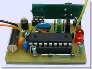
Circuit second part consists of water released into the rf-makers and the information will appear RF-receiver circuit two circuit pic 16f84 micro-controller based on the pic “Reed Relay” use and relay operation rf to convey a sample project also modules source MPLAB files (asm, hex, etc.).’s top to bottom in pdf format PCB, circuit diagrams have a list of materials
4 red LEDs and buzzer on the RF receiver circuit with the signal status can be monitored. Author of the circuit to detect fish under the water for balIkcIsI mention that 🙂 transmitter circuit must be watertight boxed says.
FISH DETECTOR CIRCUIT
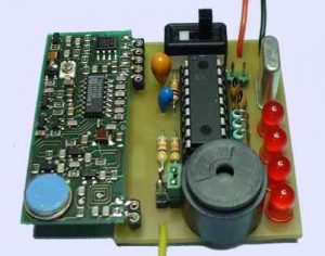
Fishing for how effective it can be useful I do not know, but the source code and presence of a hardware reed relays, RF modules use a good example also comes to my mind this circuit burglar alarm circuit as was the development picprograml with people interested in different ideas can give.
This is a set which allows the detection of transmission of the key information with HF to a receiver. Manufacturing is not within reach of a beginner. There is much work to achieve the electronic part that the mechanical part (inclusion in enclosures) The transmitter is designed to be embedded in a waterproof case and attached to a stick wedged in fishing action which it will detect the vibration sensor using a pen. Upon detection, there is transmission of an identification code to a receiver. A receiver can handle 4 sticks. At a reception, if the code is identified, a buzzer sounds and LED lights. The LED remains lit until the fisherman does not give the order of extinction. System design that 4 receivers, so a total of 16 sticks, can operate in the same environment.
source: pagesperso-orange.fr/Doumai Fish Detector schematic source code files alternative :
FILE DOWNLOAD LINK LIST (in TXT format): LINKS-8161.zip
Source: PIC16F84 RF FISH DETECTOR CIRCUIT
- How does the transmitter detect fish?
The transmitter uses a vibration sensor attached to a pen on a fishing stick embedded in water. - Can multiple sticks operate simultaneously?
Yes, the system design allows 4 receivers to handle a total of 16 sticks in the same environment. - What happens when a signal is received?
A buzzer sounds and the LED lights up when the receiver identifies the transmission code. - Is the transmitter circuit waterproof?
Yes, the transmitter must be placed inside a watertight box. - How do you turn off the alert indicator?
The LED remains lit until the fisherman gives an order to extinguish it. - What components are used in the receiver circuit?
The receiver uses a PIC16F84 microcontroller, reed relays, RF modules, 4 red LEDs, and a buzzer. - Are source files available for this project?
Yes, MPLAB files including asm and hex formats are available for download. - Does the author guarantee the effectiveness of this fishing method?
No, the author states they do not know how effective the fishing method can be.
