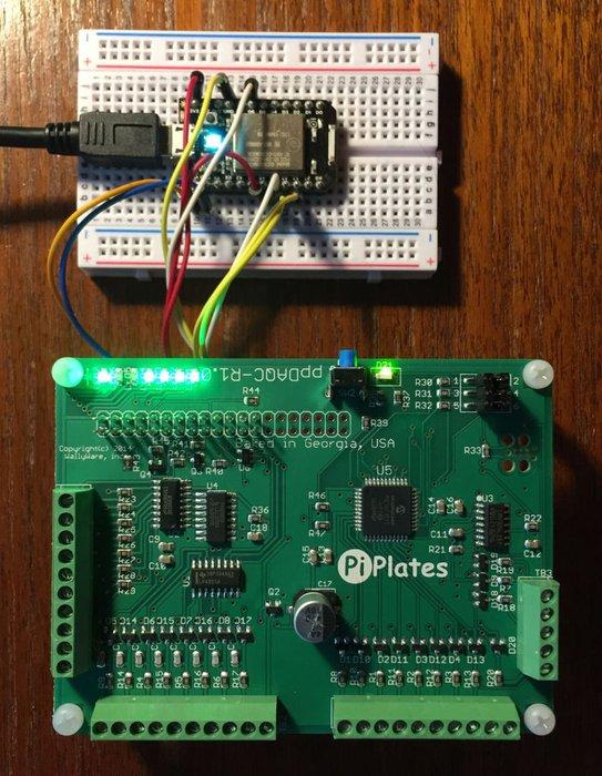
The ppDAQC board from Pi-Plates.com is an inexpensive yet powerful solution for expanding the input/output capabilities of the Spark Core. And since Pi-Plates are stackable, it is a simple task to scale up the I/O capabilities of a single Core. All that is required for connectivity are the four SPI signals (signals A2-A5) as well as a single digital output (D6). Power can come from the Core or from the ppDAQC board.
Step 1: Required Components
To build this assembly the following components are required:
1. A ppDAQC board from Pi-Plates.com
2. A Spark Core
3. A 5VDC power supply or the USB power supply included with the Core.
4. A small protoboard (currently included with the Core Evaluation kit)
5. Jumper wires
Step 2: Connections – 1
All Spark applications for the ppDAQC require three files:
1. ppDAQC.ccp – a lightweight set of library functions
2. ppDAQC.h – the header file with all of the function prototypes
3. yourapplication.ino – your application program
The application program has to have the following structure:
#include "ppDAQC.h"

extern int ppFRAME; //____ppDAQC I/O ports that are initialized below

extern int ppCE; //

void setup()

{

SPI.begin();

delay(1); // Wait 1msec

SPI.setClockDivider(SPI_CLOCK_DIV64);

delay(1); // Wait 1msec

SPI.setDataMode(SPI_MODE0); //All of these function are required for

//initializing the SPI/Pi-Plate interface

pinMode(ppFRAME,OUTPUT); //

pinMode(ppCE,OUTPUT); //

digitalWrite(ppCE,HIGH); //

//initialization for your application variables go below:

}

void loop()

{

// Your application code

}

