The Idea
So for some reason I bought 2 IKEA lamps at a flea market. As IKEA furniture has a long history of being hacker-friendly, I figured they shouldn’t be an exception to the rule.
My plan? Fit a few 10W RGB LEDs in there together with an ESP8266 to use the final result as an alarm clock.
The Schematics
When you are dealing with a LED consuming that much current, you can’t simply use a series resistor as the latter would need to dissipate R*I² in heat. I’m therefore using a dedicated LED driver that automatically adjusts the LED voltage to match a given current. As you can guess, it isn’t much different than a standard step-down and just uses a shunt resistor to measure the current flowing through the LED.
The A6211 has an adjustable switching frequency set using R2/R3/R4 (to 700KHz in our case) and an EN input meant to be connected to a PWM signal. Its datasheet is well made so you can easily find all the information needed to select your passive components values. C13/C14/C15 are here to decrease the current ripple.
The complete board is 12V powered through P1. A DC/DC is placed on the board (I was lazy) to provide the 5V needed by my ESP8266 dev board. The P3 connector therefore serves as an interface beween the latter and our main PCB.
P4 is meant as an expansion connector to which will be connected an accelerometer. The goal is to hopefully measure REM sleep cycles to gradually increase the light at optimal times.
The great thing in this project is that the ESP8266 has all the required IOs for my purpose (PWM outputs, I2C, std IOs).
The Realization
The inside of the lamp is fairly simple, I just needed to remove the socket to make room for my PCB:
That was a fun PCB to design!
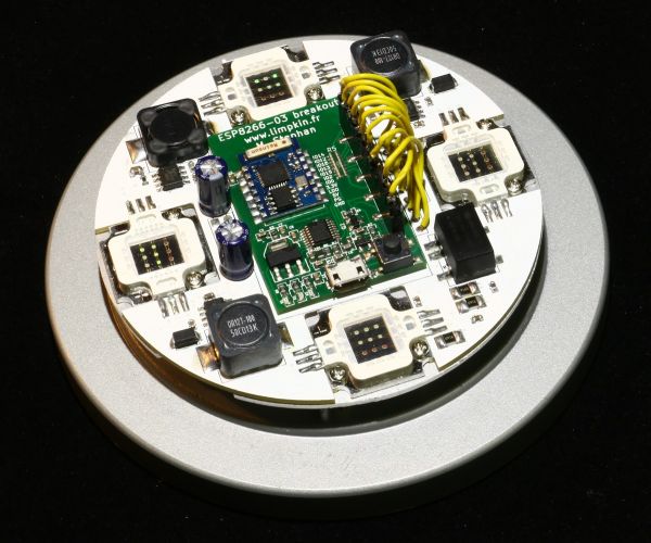
As you can see its outline is made at the right diameter and has slots in which will fit the RGB LEDs. The ESP8266 board will nicely fit in the middle. Keeping in mind that 10W LEDs don’t have a 100% efficiency, I machined an aluminum plate that will be used for heat dissipation:
In this picture you can get an idea of the stackup:After applying some heat paste and soldering the LEDs:
And this is what it looks like from below:
You can notice the M2x6mm brass standoff spacers and the power supply/expansion connector.
Here is the final result:
Obviously the USB port won’t be used 😉 .
For more detail: A Connected Lamp to Wake Me Up

