Step 1: Gather the Materials
You would be surprised at how many people neglect this step. Before you can make the Bot, you first must have all the components — because nothing is worse than getting halfway there and realizing you can’t finish it. Below is a list of materials you will need for the Boss Box Bot.
Materials:
Corel Draw (“free” versions are sufficient)
VEX PIC Microcontroller
VEX 75 MHz Transmitter and Receiver
.2 inch Wood Sheet
.19 inch Foam Board
1/8 inch Wooden Dowels (skewers work nicely)
1/4 inch Wooden Dowels
Hot Glue (or other adhesive)
Non-Slip Padding
4 VEX 2-Wire 393 Motors
Assorted VEX Components
Axles (3″ x4)
Delrin Bearing Flats (x4)
Lock Bars (x4)
Collars (x4)
Screws (x8)
7.2V Battery
Pliers/wire cutters/standard cutting utensils
Epilog LEGEND Laser Engraver
Xbox 360 Controller
Common Sense (recommended)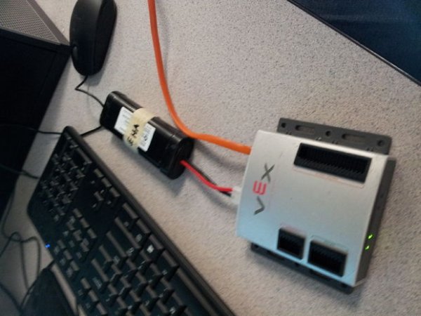
Step 2: Design
Once you’ve gathered all the materials, it is time to design the bot — and by design we mean download the parts you’ll need. Below are the AutoCAD Drawing files needed to cut it out.
Download them.
Step 3: It’s Cutting Time
For the cutting we will be using an Epilog LEGEND Laser Cutter and Corel Draw.
Open a New Corel document with dimensions 32″x20″ (wxh). Drag and drop the first file into the document, click okay when prompted, and position the piece somewhere near the top left corner. Select the geometry, right click, and select properties. Change the Line Weight to Hairline and the Color to Red: this lets the laser know it’s supposed to cut these lines, not engrave them.
Place the cutting medium into the laser cutter. The base, front, and sides should be cut from foam core; all other parts should be wood.
Click print, and adjust the print settings according to the following:
Wood: Speed 10%, Power 90%, Frequency 3500Hz;
Foam: Speed 70%, Power 60%, Frequency 2500Hz;
Make sure to change the paper size in Print Settings to match the document, otherwise none of the part will print — even if some of it resides in the 8.5″x11″ default.
Run the job on the cutter. Regardless of the material, each job should be run at least twice.
Rinse and repeat until all parts are cut out.
NOTE: As time goes by — and the laser’s tube heats up — more and more passes may be required to cut through. If the laser starts dying, walk away for ten minutes or so to allow it to cool. It’s recommended that you run the larger parts as several individual jobs, splitting them apart in Corel (right click, ungroup, and delete some of the geometry). Run the more complicated aspects of the parts first — i.e. the wood connectors — to ensure the more crucial parts get cut cleanly; straight lines that don’t cut all the way through can be “persuaded” with a razor or other sharp object.
You need to cut out the following:
4 Bases (foam)
4 Sides (foam)
4 Fronts (foam)
24 Wheels (foam; 12 with round axle holes, 12 with square)
8 1.5″ Gears (wood; 4 with round axle holes, 4 with square)
4 2″ Gears (wood)
2 Short Cross Bars (wood)
2 Long Cross Bars (wood)
2 Inner Axle Supports (wood)
2 Outer Axle Supports (wood)
1 Centre Support (wood)
4 Axle Holders (wood)
4 Axle Holder Inner Caps (wood)
4 Axle Holder Outer Caps (wood)
Step 4: Assembly: Part 1
Before you begin, ensure you have all the parts from the previous page AND the following:
4 VEX Axles (or equivalent .125″ square bar)
.25″ Diameter Wooden Dowels
.125″ Diameter Wooden Dowels/Skewers
4 VEX 2-Wire 393 Motors
4 VEX Flat Delrin Bearings
4 VEX Lock Bars
The Base
First, take two of the base pieces and glue them together, ensuring they’re lined up fairly well (only worry about gluing around the edges; it’s more important to secure the connectors than the center).
Then, take two of the front pieces (the shorter of the foam walls) and glue them together, making sure to line them up as well. Do the same with the other two fronts.
Now, carefully fit the base’s pegs into the slots on the walls as shown in the last picture. Be sure not to put too much pressure on any one point on the walls; if it isn’t going on, wiggle it around, but don’t force it: it’s designed to fit snugly.
DO NOT fit the sides on at this time.
Step 5: Assembly: Part 2
The Interior
Now it’s time to insert all the wooden interior supports to ensure the robot doesn’t just fall apart under its own weight.
First, take the two Inner Axle Supports and fit them in to the inner pair of slots in the front. Slide them all the way through until they go into the corresponding slot on the opposite side.
Then, take the Outer Axle Supports and do the same thing, this time with the two outermost holes. The final central pocket is for the Centre Support; slide that one in last. Ensure all 5 supports are lined up with one another: their slots should be in roughly the same place, and looking perpendicular to the supports you should be able to see all the way through the ones on the end.
Next, take the two Long Cross Bars and line their slots up with the endmost ones on the supports. Push the Cross bars down, interlocking the slots. As with the base, don’t force anything; if it isn’t going, try repositioning it and trying again. Push each slot only a little at a time to prevent chipping or breaking. The bars should fit snugly into the slots, and they should end up roughly flush with the top of the supports.
Now, find the two shorter Cross Bars; fit these into the innermost slots on the supports, following the same procedure as before. These should also end up flush.
Step 6: Assembly: Part 3
Now that the structure of the Bot is complete, it’s time to assemble the moving components.
Wheels: Direct-Driven
For each of the four Direct-Drive wheels, you’ll need the following:
3 Wheels w/ Square Hole
1 1.5″ Gear w/ Square Hole
1 Axle Holder
1 VEX Lock Bar
Inner and Outer Axle Holder Caps
.125″ Dowels/Skewers
VEX Square Axle (or equivalent .125″ Square Bar)
Hot Glue or other adhesive
Something sharp (like clippers)
First thing’s first. Take the three wheels and stick the VEX Axle through them. This lines up the .125″ holes for the dowels. Take 4 dowels and stick them through the holes in the wheel. Lay the wheel stack flat on the table with the dowels sticking up. Trim them so that they stick up between 1″ and 1.5″.
Turn the wheel over and put a thin layer of hot glue over each of the axle holes; this is more to keep them from sliding out than it is to secure them (since the whole purpose of the dowels is to support against torsion, it really doesn’t matter how much they slide around, so long as they don’t fall out).
Turn it back and line the Gear up with the dowels. Slide it down all the way until it touches the uppermost wheel. Slide the Outer Axle Holder Cap (the one with more holes) down in the same manner. Now, pushing down on the assembly firmly, trim the dowels as closely to the Cap as possible; then, hot glue them in place with a thin layer like the other side.
Next, take 4 more dowels. Put a small amount of hot glue in each of the outer holes on the Cap (the one’s without dowels in them already), then place the dowels in the holes and push down firmly — the Gear prevents them from coming out of the other side, so don’t worry about that.
Take the Axle Holder and slide it down the newly-attached dowels, but don’t glue it. Take one of the VEX Lock Bars and fit it into the holder, sliding an axle through it: this ensures everything’s lined up correctly. Leave the lock bar in the slot.
Take the Inner Axle Holder Cap and slide it down the dowels; push firmly on it, trim the dowels, and hot glue them like before.
That constitutes one of the direct-drive wheels for the Bot. Now make 3 more.
Step 7: Assembly: Part 4
Wheels: Gear-Driven
For each of the four Gear-Driven Wheels, you will need the following:
3 Wheels w/ Round Holes
.125″ Wooden Dowels
.25″ Wooden Dowels
1.5″ Gear w/ Round Hole
Hot Glue
First, take one of the wheels and fit a .125″ dowel through one of the smaller holes; fit the other two wheels onto the same dowel in the same manner. Then, slide the other 3 dowels into the holes in the newly-made stack. Lay it flat on the table so the dowels stick up. Trim them so they stick up about 1″ in length.
Turn the wheel stack over and apply hot glue to the dowel holes like you did with the Direct-Drive Wheels.
Take the Gear and line it up with the dowels; then, slide it down so it touches the wheel. Push firmly on the stack, trim the dowels closely, and hot glue them as before.
This constitutes one of the Gear-Driven wheels for the robot. Make 3 more before moving on.
For more detail: The Boss Box Bot
About The Author
Ibrar Ayyub
I am an experienced technical writer holding a Master's degree in computer science from BZU Multan, Pakistan University. With a background spanning various industries, particularly in home automation and engineering, I have honed my skills in crafting clear and concise content. Proficient in leveraging infographics and diagrams, I strive to simplify complex concepts for readers. My strength lies in thorough research and presenting information in a structured and logical format.
Follow Us:LinkedinTwitter