
Summary of PIC32MX: Interfacing to a Secure Digital (SD) Flash Card
This project aimed to interface a PIC32MX460F512L microcontroller with a 2GB FAT32 SD card using SPI communication for data storage. Based on tutorials by Lucio Di Jasio, the team developed functions to initialize and attempt read/write operations. Although hardware configuration was verified correct and initialization succeeded, the final read/write demo failed due to suspected code errors. The setup included specific resistors and LEDs for status monitoring but did not successfully complete the assignment tasks of writing or reading 1000-byte files.
Parts used in the PIC32SD Card Interface Project:
- PIC32MX460F512L Microcontroller
- 2GB FAT32 SD Card
- SD Card Holder (11 pins)
- 10K Pull-up Resistors
- 1K Pull-up Resistors
- Green LED (Write Protect indicator)
- Yellow LED (Card Detect indicator)
- Mini-USB Connection (for 3.3V power)
Original Assignment
Do not erase this section!
Your assignment is to create code that will allow the PIC32 to read and write data to a FAT32 SD card. The SD card should be able to be read by a PC after data has been written on it by the PIC32.
Create functions so that it is easy to read, write and initialize the SD card.
Use the example projects in the “Microchip Solutions/USB Device – Mass Storage – SD card data logger” and “Microchip Solutions/USB Device – Mass Storage – SD card reader” folders as a guide.
Use your code to create a folder on the PIC32 and write 1000 bytes of data to a text file in that folder. How long does it take? Make sure the PC can read the file.
Create a folder on the SD card with the PC and place a text file in the folder with 1000 bytes of data. Read the file with the PIC32. How long does it take?
Overview
Secure digital cards, or SD cards, are inexpensive and common mass storage devices that can be interfaced with our PIC to provide a larger non-volatile data storage space. Non-volatile memory is computer memory that retains information even when not powered. In this lab, we interfaced our PIC32MX460F512L to communicate with a 2GB FAT32 SD card to allow reading and writing of data.
The original program stems from tutorials from the book Programming 32-bit Microcontrollers in C: Exploring the PIC32 by Lucio Di Jasio. We used the tutorials from Day 14 and 15 to generate our code for SD card reading and writing via SPI communication (Serial Peripheral Interface). The main problem with this tutorial is that it is made for the PIC32MX360F512L on the Explorer16 board, so many changes were required in order to run the code.
NOTE: While ultimately, we were able to initialize the SD card and send data along the output and input lines, we were unsuccessful in executing the read/write demo. We are confident that the hardware configuration and circuit are correct, however the code likely contains errors.
Circuit
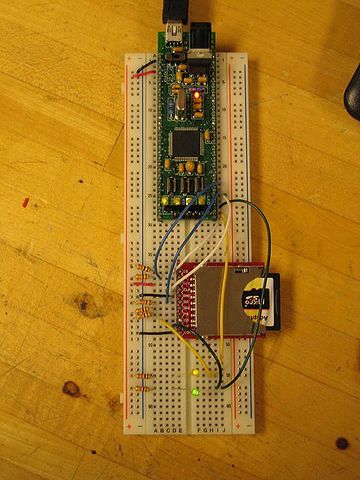
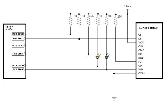
The SD card holder has 11 pins, 6 of which are being directly used for communication with our PIC. The SD card is powered off of 3.3V from our PIC, which comes from our mini-usb connection. 10K and 1K resistors pull-up resistors were added to each connection in order to allow for a voltage drop. Green and yellow LEDs were added to the Write Protect (WP) and Card Detect (CD) lines for ease of use. A powered yellow LED indicates the presence of an SD card in the SD card reader. A powered green LED indicates that the Write Protect is off. No resistor is necessary on the clock line. The IRQ and P9 pins on the SD card holder were not needed for SPI communication, so they were not connected to the PIC. However, they need to be powered for the SD card holder to operate properly. A breakdown of each of the 11 pins on the SD card holder is displayed in the table below.
NOTE: While ultimately, we were able to initialize the SD card and send data along the output and input lines, we were unsuccessful in executing the read/write demo. We are confident that the hardware configuration and circuit are correct, however the code likely contains errors.
Circuit
The SD card holder has 11 pins, 6 of which are being directly used for communication with our PIC. The SD card is powered off of 3.3V from our PIC, which comes from our mini-usb connection. 10K and 1K resistors pull-up resistors were added to each connection in order to allow for a voltage drop. Green and yellow LEDs were added to the Write Protect (WP) and Card Detect (CD) lines for ease of use. A powered yellow LED indicates the presence of an SD card in the SD card reader. A powered green LED indicates that the Write Protect is off. No resistor is necessary on the clock line. The IRQ and P9 pins on the SD card holder were not needed for SPI communication, so they were not connected to the PIC. However, they need to be powered for the SD card holder to operate properly. A breakdown of each of the 11 pins on the SD card holder is displayed in the table below.
NOTE: While ultimately, we were able to initialize the SD card and send data along the output and input lines, we were unsuccessful in executing the read/write demo. We are confident that the hardware configuration and circuit are correct, however the code likely contains errors.
For more detail: PIC32MX: Interfacing to a Secure Digital (SD) Flash Card
- What type of memory is an SD card?
SD cards are inexpensive and common mass storage devices that provide non-volatile data storage space. - How does the PIC32 communicate with the SD card?
The PIC32 communicates with the SD card via Serial Peripheral Interface (SPI) communication. - Which microcontroller model was used in this project?
The project utilized the PIC32MX460F512L microcontroller. - What voltage powers the SD card in this circuit?
The SD card is powered off of 3.3V from the PIC, which comes from the mini-usb connection. - Why were pull-up resistors added to the connections?
10K and 1K resistors were added as pull-up resistors to allow for a voltage drop. - Does the clock line require a resistor?
No resistor is necessary on the clock line. - Which pins on the SD card holder were not connected to the PIC?
The IRQ and P9 pins were not connected to the PIC because they were not needed for SPI communication. - Did the project successfully execute the read/write demo?
No, the team was unsuccessful in executing the read/write demo despite successful initialization.
