
Introduction
Whac-A-Mole (Mogura Taiji) is a popular carnival game that originated from Japan; it involves the player whacking a mole that can appear out of one of five possible holes. Over the years, as the game grew in popularity internationally, many variations of the game have been introduced. Please see https://en.wikipedia.org/wiki/Whac-A-Mole for further information.
Our project is heavily inspired by the Whac-A-Mole game. A game will consist of a very fast sequence of small time windows, in which a player gains points by pressing the correct button before the opponent does. To make the game more exciting, the buttons light up in a random pattern on the game board with random delays in between each press. There is a screen on the game board that keeps track of the players’ scores and indicates the game’s progress.
Whack-a-Button Demonstration
Development Process
We started the project by designing the hardware system, including the mechanical box and the button schematics. At the same time, we performed basic software testing using one LED button. Once the hardware was solidified, we started programming the one-player whack-a-mole game incorporating the TFT screen and the start button. We then moved on to designing the two-player game. Such a systematic approach allowed us to debug quickly without having to consider too many components at once.
High-Level Design
The whack-a-mole game has been recreated by many online communities. Most of them are on platforms such as Arduino (https://www.101computing.net/arduino-whack-a-mole/), and their designs are simplified for beginners and are lacking the original game setup. Originally, we wanted to build the game with physical moles using either servos or linear actuators, but due to time and budget constraints we decided to use LED buttons and spend more time perfecting the gaming experience.
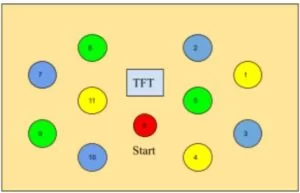
The gameplay is as follows; the red, center button flashes until a player presses it to start the game. After a 3-second countdown, the system enters the main state, during which it lights up a symmetric pair of buttons after a short, random delay, and waits for a player to press it. The first player to press the button obtains a point, and the process repeats until the game duration ends. Once the game ends, the screen displays the winner and the scores of the two players. Pressing the flashing red button returns the system to the start-state.
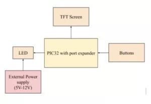
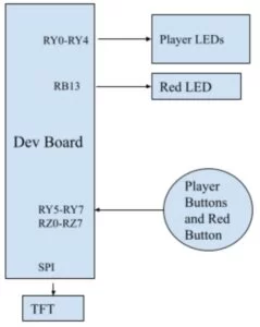
The below figure shows the block diagram of our whack-a-mole game. We are using eleven buttons where each player has five buttons and a middle button for starting the game. Each button is associated with an input and an output LED, and there weren’t enough GPIO pins available for 22 signals. To solve the problem, we first considered using two 3-to-8 digital muxes, but using muxes could potentially make the software more complex on top of the gaming logic. We then decided to solve the problem in hardware where two symmetric LEDs are wired to the same GPIO pin on the port expander. This worked because during the game, the buttons the players were competing to press were assigned symmetrically.
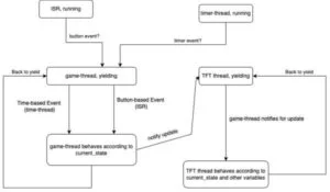
The software that runs the system consists of mainly five parts; the main function, the game-thread, the timer-thread, the TFT-thread, and finally an ISR. At a high-level scope, the main function is responsible for all initializations, while the ISR consistently performs a “sweep” through the input ports (via the port expander), updating 11 FSMs that each are responsible for one button. All these software components communicate as shown in figure 2 below.
The timer-thread is an extremely simple thread that approximates the system time by incrementing a timer variable, then yielding for a second. Two factors that progress the system are time-based and button-based events; thus, the two other threads yield for the majority of the time by using the PT_YIELD_UNTIL mechanism and activates only when the timer thread or the ISR indicates a time-based event or a button-press event.
Specifically, the game-thread yields until notified to continue by the timer thread (via time-event) or the ISR (via button-event). Once the game thread detects a need to update the TFT screen, it notifies the TFT-thread to update the display using a volatile variable. The implementation of these functions are detailed in the next section.
As far as we are aware, there are no parts of the design that may be dangerous, as the linear servos / actual moles were replaced by buttons, and there are no ethical issues to our design that would breach the IEEE Code of Ethics.
Software Design
The main function performs all initializations for the protothread library, TFT, port expander used for the buttons, and the timer for the ISR. It then uses a round-robin scheduler to schedule the three threads. The port expander is initialized as follows: ports 0 to 7 in the Z-port and ports 5 to 7 in the Y ports are set to inputs with a pull-up configuration. Ports 0 to 4 in the Y port are set to outputs, and each port controls symmetric button pair’s LEDs. The red button’s output is specially configured to be the digital pin 13 (its inputs are still detected through the port expander).
The timer thread approximates the game duration in second-resolution by repeatedly yielding for 1 second, then incrementing the global sys_time_second variable. This variable can be incremented by this timer and reset by other threads, and its value is sometimes used as a trigger in the PT_YIELD_UNTIL statements (a.k.a. time-events).
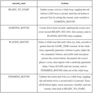
The game thread consists of a forever-while loop, and all its code is encased in a switch statement that depends on the current_state variable. This variable is a volatile, enum-typed, global variable that can take one of the following values: READY_TO_START, STARTING_ROUND, PLAYING_ROUND and FINISHING_ROUND. While the current_state variable is used to determine actions by both the game thread and the TFT display thread, only the game thread is able to increment or modify this value. The game thread’s actions are as follows:
The TFT thread yields until the variable update_screen is toggled to 1. It then immediately sets this value back to 0, and updates the TFT screen according to the current_state variable. The update_screen variable is modified only by the game thread, and the game thread does so only when it detects new information that should be updated on the TFT screen.
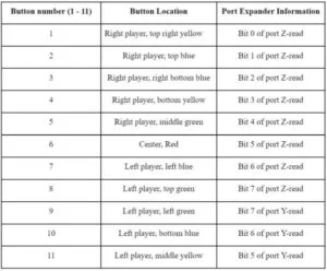
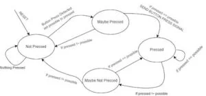
The ISR is responsible for maintaining 11 different button FSMs (one for each button). It does so by using two 11-length arrays of buttonState enums – button_states and next_button_states. It first performs full reads of both the Y and Z ports, and masks the Y port with the value 0b11100000 (only bits 5, 6 and 7 are used in the Y port for inputs). Below is the mapping between the port expander’s bits to the actual buttons:
The ISR then performs a for-loop for each button; for button ‘i’, it will check the appropriate bit in either of the full-read values from Y or Z. If the bit is set, a button press is detected; otherwise, a button press is not detected. The ISR then uses this information to update the corresponding button_states and next_button_states arrays; the possible enum values are NP, MP, P and MNP, which stand for Not Pressed, Maybe Pressed, Pressed, and Maybe Not Pressed, respectively. The figure below depicts the FSM for one of the buttons (there are a total of 11 of these FSMs being updated).
Hardware Design
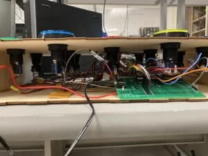
The mechanical structure of the game is a wooden box that encloses all the hardware. Only the buttons and the TFT screen are visible to the players. The box is cut using ¼ inch plywood with finger edge joints, and the joints are glued together to add extra support.
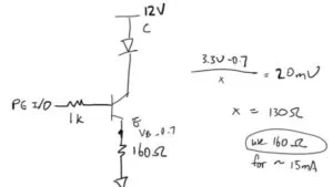
The main hardware component is the 60mm large arcade button with LED. It has four pins(figure 5): the left and right pins are to power the LED up to 12 V (with a built-in resistor), and the top and bottom pins are for button detection. Considering the brightness of the LED, we decided to use a BJT and power the buttons externally using a power supply (figure 6). The base of the nmos is connected to the port expander input through a 1K ohm resistor as a current limiter; the emitter of the nmos controls the current going through the LED via a 160 ohm resistor when the nmos is on; the collector is connected to one side of the LED so when the nmos is on, current flows from the power supply to ground. The value of the emitter resistor is selected to keep the LED current around 15mA. The LED turns on when the VBE(voltage from base to emitter) is above the turn-on voltage (~0.7 V), allowing the current to flow through from the power supply to ground.

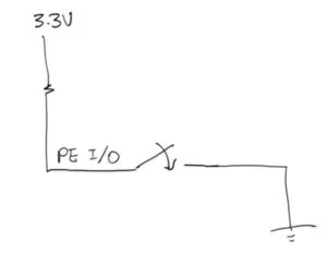
The two button pins of the arcade button are wired as figure 7. One side of the button is wired to ground, and the other side of the button is connected to a port expander I/O that’s pulledup. When the button is pressed, the I/O pins detect low as the circuit closes. Originally, we wired the left side to a pulled-down I/O input and the right side to 3.3V. This did not work because the input side was floating when the button wasn’t pressed, causing flicky button detections.
As mentioned above, two LED outputs, one from each player, are wired to the same output pin on the port expander due to I/O limitation. All the LED outputs and button inputs are wired to the port expander except for the red button LED output. The hardware pin mapping is shown below, where RY0-RY4 from the port expander and RB13 are output LEDs and RY5-RY7,RZ0-RZ7 from the port expander are active low inputs.
All the hardware components are prototyped on a breadboard and later moved to a protoboard. This prevents any loose wires from interfering with our debugging process.
Results and Conclusion
The project was overall a success; the system is responsive and interactive with both users at the same time, and the “sweeping” mechanism of the button inputs using the ISR is, for the most part, bug-free and functional. When the ISR is run at a low frequency, there are instances where, when two players press a button at the same time, the ISR fails to detect one of them. During critical moments of the game, this very rare occurrence resulted in a short freeze of the system; our solution was to shorten the ISR’s code and increase its frequency significantly, which reduced the chance of this happening to nearly never.
Nonetheless, using the ISR for button input detection was a design choice that we made out of many other possible approaches, such as polling and interrupts. The use of polling for button presses only when presses are necessary would probably reduce the frequency of unresponsive presses, but is not very feasible when considering that polling will be blocking all other threads (TFT update, timer, …). Interrupts also may have worked, but combining interrupt-based inputs with the port expander and the 11 button FSMs would have created significantly more complex and slow code. Most importantly, however, most threads performing significant computations are yielding for the majority of the time, so an increased frequency in the ISR was acceptable for real-world gameplay.
One of the most significant debugging sessions resulted from the fact that the ISR was outputting false button presses for the short period of time in between its initialization and the initialization of other variables related to the button FSM. This simple but subtle issue resulted in the button FSM frequently being at the wrong states when the game started, resulting in unresponsive buttons and false-detects.
Another issue we encountered was the floating input pin on the button. Originally, we wired one end of the button to a GPIO pin and the other end to 3V3. During software testing, we noticed that not all our buttons can be detected properly, and some buttons take multiple presses to be recognized. After consulting with the TA, we realized that the button input pin is floating when not pressed given that there’s no pull-down option on the port expander pins. We then reconfigured the circuit so one end of the button goes into a pull-up GPIO pin and the other end goes to GND. In the case where the button is not pressed, the GPIO pin detects HIGH due to the internal pullup, and it detects LOW when the circuit is closed.
As far as we are aware, there are no parts of the design that can hurt any players, as the linear servos / actual moles were replaced by buttons, and there are no ethical issues to our design that would breach the IEEE Code of Ethics as well. There are no reasons for a player to press the opposing player’s buttons, so the buttons should not be contested by more than one player as well.
While the design itself was reverse-engineered from a concept that was inspired heavily from the popular Whac-A-Mole game, all the code was written from scratch except for small references to parts of the previous labs (Protothreads interface, button FSM, ISR setup). As far as we are aware, there are no trademark/patent issues with regards to a game that involves pressing a button faster than the opposing player. There are no patent or publishing opportunities for our project, as it was a reverse engineering project of a common arcade game.
Overall, we were able to complete and optimize our design as expected. If we had more time, we could implement a buzzer that adds audio effects to our whack-a-mole game. If we were to redo the project again, we would protoboard the circuit earlier in the design to ease our debugging process. We spent tons of time figuring out if a bug was a software issue or a hardware issue, and solidifying the hardware earlier could’ve saved some time for us.
Source: Whack-a-Button
About The Author
Muhammad Bilal
I am a highly skilled and motivated individual with a Master's degree in Computer Science. I have extensive experience in technical writing and a deep understanding of SEO practices.