Introduction
If you move a bright light fast by the eyes, it will leave a line behind because the human brain and eyes are slow to interpret fast changes in light intensity, leaving an afterglow. If a row of LED’s is moved sideways while the LED’s intensity is changed, an image will shortly visualize in the air where the LED’s are moved. If this is done several times, for example if the LED’s are mounted on the end of a bar mounted on a motor as in the figure on the right, the same area in the air could be scanned several times showing the same image each time. Done at high speed it would generate a quite good virtual display hanging in air thanks to the persistance of vision effect of the brain. People has started to refer to this kind of display as POV-displays (Persistance of vision displays) as if it was the only type of displays depending on the peristance of vision effect but that is kind of ignorant as many display types use the same effect, like for example CRTs and multiplexed LED displays, thus “mechanically scanned display” is a more accurate name.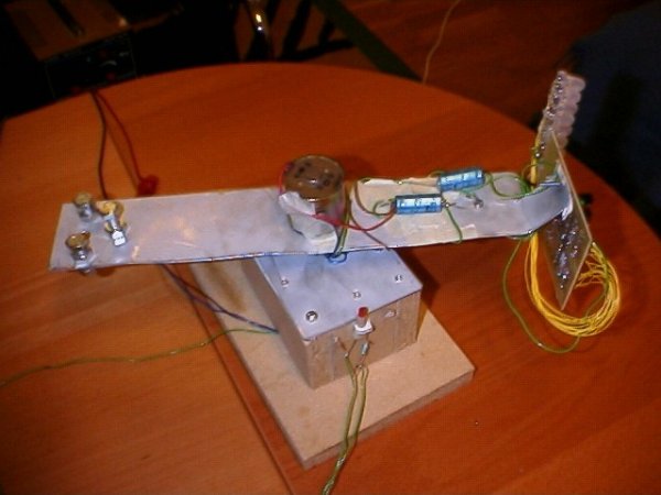
The idea of making a mechanically scanned display came from Bob Blick’s mechanically scanned clock. He made a clock using the same technique, so I wanted to take his idea a step further and make games with it, resulting in this project. The biggest problem to do this was the communication between the game system and the graphics card. This was not a problem for the original mechanically scanned lock because in that system the clock-functionality was built in to the graphics card. So no communication was needed for the clock.
The mechanics
The mechanics is an essential part of this project since it is a mechanically scanned display. The system has basically two parts, one solid platform, and one rotating rotor. The rotor is a bar, with the graphics card in one end, and a balance weight in the other. On the graphics card, a Plexiglas bar is attached, with 16 LED’s (10mm) attached on it. To get a wider viewing angle of the LED’s they have been made rugged with sandpaper.
To get a more stable rotor, the motor is attached and rotating with the rotor, and the axle is mounted at the platform. The motor has an extra long axle, so the three ball bearings, for power supply and communications can fit between the rotor and the platform.
Communications
One of the hardest problems in this project has been the communication between the rotor and the platform. The mechanically scanned clocks that have been done before didn’t communicate with anything, the clock functionality is in the microprocessor that is rotating with the rotor. The power supply have been transmitted to the rotor in many different ways, for example by taking it from the rotor of the motor that is getting it through coal contacts, or some people have used bearings, but my choice was to use ball bearings with wires soldered to them. First when only the power supply was to be transmitted through them, it seemed ok, but as I first tried to communicate between the two PICs the result was catastrophically bad. As the bearing was not conducting all the time due to micro gaps, it was impossible to do any communication at all, when looking at the signal it was full of noise, but the power supply didn’t have this problem.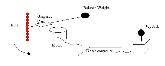 So I tried to increase the current to 100mA when communicating, and it really decreased the noise by breaking through some of the micro gaps. Now it was possible to see the information clearly, but the amplitude was lower and it had a quite big offset from the ground level of the game system. This was due to there is some resistance in the bearings, and when running a big current through them, there was a quite noticeable voltage drop. The voltage difference problems was solved by removing the DC component of the signal with a capacitor and add a bias voltage (VDD/2=2.5V). Now it was possible to get a clear signal by using an operation amplifier to compare the signal with an adjustable reference level. The communication problems were solved! The same circuit for communication is used for both the graphics card and the game controller.
The graphics card
The graphics card controls the LED’s, these are driven by two 74573 latches. These are connected to Port B, and the latches are selected with the two lower bits of Port A. To limit the current through the LED’s there is one 270 current limiting resistor on each LED. The synchronizing IR.-switch is inputted at pin 2 of the Port A, giving a positive pulse as the IR.-switch passes the IR.-led. The IR led is placed inside of a tube, to make the IR beam more narrow, giving a more stable picture.
The communication interface is connected to pin 2 and pin 3 of Port A. Using a standard voltage regulator (7805) the 5v-supply voltage is achieved. Because of the noisy environment, both sides of the regulator got big capacitors to reduce noise.
For more detail: Virtual Game System – A game console with a mechanically scanned display.
About The Author
Ibrar Ayyub
I am an experienced technical writer holding a Master's degree in computer science from BZU Multan, Pakistan University. With a background spanning various industries, particularly in home automation and engineering, I have honed my skills in crafting clear and concise content. Proficient in leveraging infographics and diagrams, I strive to simplify complex concepts for readers. My strength lies in thorough research and presenting information in a structured and logical format.
Follow Us:LinkedinTwitter