
USB connected TI TMS320F28027 based ZRLC Tweezers with
Most Digital multi-meters measure Resistance and Capacitance and LC-meters can measure Inductance and Capacitance. Presented here is a ZRLC meter which can measure Resistance, Capacitance, Inductance and Complex Impedance.
The hardware is built around a TMS320F28027 micro-controller an 8-port-analog-switch ADG714 from analog-devices and a Microchip rail-to-rail dual operational-amplifier MCP6022.
The hardware details, .Hex file for the TMS320F28027 micro-controller and the VS2013 .Net 2.0 files for the PC GUI are provided in this Instructable.
The Source-Code ( TI CCS5.5 C-Code and VS2013 VB.Net-Code) is shared at the GitHub repository: https://github.com/ajoyraman/Aj_ZRLC_Tweezers .
A manual Impedance mode permits experiments and teaching of magnitude, phase and complex impedance concepts.
This hardware will form an invaluable tool for electronics students and hobbyists working with SMD components.
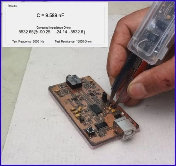
Step 1: Principle of Operation
This application is based on the principle of measuring the voltage (amplitude and phase) across an unknown Impedance when fed a sin-wave of known frequency and amplitude through a known resistance.
The hardware is built around a TMS320F28027 micro-controller an 8-port-analogue-switch ADG714 from analogue devices and a Microchip rail-to-rail dual operational-amplifier MCP6022.
A High-Frequency PWM waveform is generated in the micro-controller and modulated by a 64-Bit sin-wave sequence. This when filtered and buffered forms a sin-wave source ( select able 300Hz, 3kHz, 30kHz). The sin-wave source is connected to one of 4-resistors (100, 1k, 10k, 100k) using the analogue-switch. The selected resistor being connected to the unknown Impedance whose second terminal is connected to ground.
Once a frequency and resistance have been set the sin-wave is generated on command and 128 10-Bit samples of Vout (signal-source) and Vin (Voltage at unknown Impedance) are A/D converted and stored in internal memory.
This data is transferred to a PC through an USB port using an USB-to-TTL converter, which also powers the hardware.
Suitable digital-signal-processing on the PC using the VS2103 GUI software displays the real and imaginary part of the unknown Impedance. This is interpreted as Resistance, Capacitance, Inductance or Complex Impedance.
For more detail: USB Tweezers for ZRLC measurements
About The Author
Ibrar Ayyub
I am an experienced technical writer holding a Master's degree in computer science from BZU Multan, Pakistan University. With a background spanning various industries, particularly in home automation and engineering, I have honed my skills in crafting clear and concise content. Proficient in leveraging infographics and diagrams, I strive to simplify complex concepts for readers. My strength lies in thorough research and presenting information in a structured and logical format.
Follow Us:LinkedinTwitter