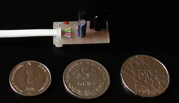
The UIR is a device that enables you to control your PC with ANY remote controller you have (TV, VCR, CD or Stereo). Original hardware & software was designed by Martinus & Ties Bos. You should check their site first. There it was, now it has either moved or is unavailable. In this article you can find improved and simplified hardware scheme, software & hints for building the device.
The device is very simple: minimal version uses only 3 components! So if you are not planning a big serial production you will build it on experimental (universal) circuit board. This is the most correct schema:
Schematic changes explanation/discussion:
- Cond’s on quartz are used for oscillator frequency stabilization, oscillator startup etc. UIR works with RC oscillator which is far more inaccurate. If you are planing to use UIR in ‘normal’ environment (your room) these are not needed.
- 5V1 on RS232 TXD is also not needed because there is one inside PIC port, especially as maximal current is limited with R1 (100k).
- Circuit needs 7mA (2mA PIC + 5mA SFH according to datasheets) when it’s not sending data to PC, which can be supplied by RS232 RTS. When sending data it depletes RTS and reserve stored in C1. This solution is 0.25 DM (0.1$) more expensive but has less parts, better exploits available current and is more reliable. The hidden gain is that now you can use 4 wire OLD MICE CABLE to connect UIR to PC!
This, however is not the simplest schema: you can replace 78L05 with single 5V1 zener (4V7 or other wont work: The SFH demands 5V). In that case, you are risking excessive RS232 port current burning zener diode, wich shouldn’t happen because RS232 port current is limited. Also you can omit 100uF (or use smaller value) wich is used as reserve current source in case the circuit needs more current than it gets through RS232 (in a moment). Also, you don’t need 1N4148: it’s there only to assure current direction, wich cannot change due to RS232 port design. Only 4 parts are needed: PIC, 5V1, SFH and 100k. Cool. Hmm, could we do without 100k? Yes, the protection diode on PIC port will probably survive …
Nowafter you decided what schema to use, the biggest problem is choosing and programming the microcontroller. You can use almost ANY Microchip PIC microcontroller, but software is prepared for PIC12C508/509 (512B/1024B OTP) and PIC16C84/F84 (1K FLASH, C84 is old version). So if you have to buy the microcontroller, PIC12C508A is your choice (cheapest PIC, at least were I buy it). Originally, I used a 16C84 leftover.
When programming, folowing configuration bits must be set:
- PIC12C508/509: OSC XT for use with quartz, OSC IntRC for internal oscillator; WDT ON (watch dog timer); MCLRE INT (internal startup)
- PIC16C84/F84: OSC XT; WDT ON (watch dog timer);PWRTE ON
Configuration bits are set correctly within the hex files, but doublecheck them anyway.
For more detail: Universal Infrared Receiver using PIC16F84 and PIC12C508

