
*** There’s a firmware update. Please check out! ***
LEDs are taking over conventional lighting every day. High-power LEDs over 1W are becoming more and more affordable, and I wanted to start using them to replace the lighting fixtures around me. However I realize that finding and configuring the power supply was a bit of a pain, since I wanted to use different LEDs in different configurations depending on what the lighting was for. Power supply needs to regulate the current that goes though the LEDs. With higher current that high-power LEDs require, active constant current circuit is the only practical option. Commercially available buck regulators are easy to use, however, they are usually made for a specific current and voltage range. For me that means having to purchase variety of buck drivers.
Also, most of LED drivers lack dimming function, or have poorly functioning dimmers. I think dimming is essential for modern lighting, and I want smooth control of brightness.
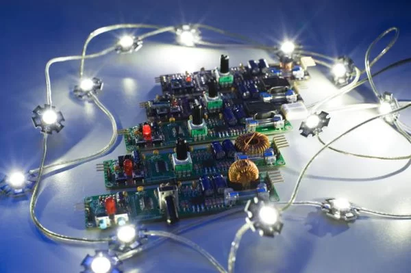
So I decided to develop a universal, dimmerable high-power LED controller. It has taken me four months to develop this controller. Although it’s still in development, I think it’s quite useful to all DYI’ers with LED lighting projects.
I made this an Open Source project. Both hardware and software are open – please use, and extend this project and share the knowledge. A 3D printable enclosure as well as couple of LED mounting hardware is also available as Open Source, download-able at Thingverse. Together you can really kick start LED conversion of your household lighting!
Here’s the list of main features:
- Inductor “switch mode” controller for high energy efficiency.
- Wide supply voltage range of 5 to 18V (can go higher, but not tested). Great with batteries as well as AC adapters.
- Up to 20W maximum output power (can go higher with active cooling). (at supply voltage 12V or above)
- Constant current (pulsed) – configurable up to 3A peak current.
- Selectable between buck-boost and boost mode.
- Analog style dimmer control (smooth, flicker-free continuous adjustment)
- IR remote receiver – controllable via Sony IR remote control
- Digitally controlled dimming – via external microcontroller including Arduino.
- Master/slave gang dimming – connect multiple units together and control the dimming from any one of the units.
- High frequency pulse drive – 32kHz to 175kHz – no flicker even in video!
This circuit is a relatively straightforward implementation of switch mode voltage converter. An inductor works to convert electric energy into magnetic energy, then it converts back to electric energy. By controlling the charge time you can control the output voltage.
My implementation is a bit different from typical boost or buck-boost circuit in that, instead of rectifying the output voltage, the output voltage drives LEDs directly (pulsed drive). This implementation provides a few advantages:
- Reduced part count.
- Higher overall energy efficiency (because rectifier has voltage loss)
- Better dimming characteristic.
In practice, you can connect 1 to 20 LEDs to the controller. Depending on the supply voltage you can choose between buck-boost or boost mode.
Buck-boost mode can supply output voltage lower and higher than the input voltage. However, efficiency suffers at higher output voltage, so boost mode should be used when you need higher output voltage than input.
Boost mode can only supply output voltage higher than input. As LEDs need minimum voltage (usually about 2V per LED) to start lighting, boost mode is effective when supply voltage is below 2 x (number of LEDs).
More on configuration later…
Peeking into the Output
I think looking at the waveforms will give you the best understanding of how this circuit drives the LEDs. As you can see in the picture, the unit is hooked up to an oscilloscope. Using two inputs, output voltage and the inductor/LED current are shown simultaneously.
The squarish wave is the voltage, and triangular wave is the current.
Notice how at the low power/dimmed level, both the current and the duty rate are low. As you increase the power level, both the current and the duty rate increases. This scheme results in a very wide dimming range with minimum color shift.
For more detail: Universal High-Power LED Driver with 3D-printable Case using PIC16F1823
About The Author
Ibrar Ayyub
I am an experienced technical writer holding a Master's degree in computer science from BZU Multan, Pakistan University. With a background spanning various industries, particularly in home automation and engineering, I have honed my skills in crafting clear and concise content. Proficient in leveraging infographics and diagrams, I strive to simplify complex concepts for readers. My strength lies in thorough research and presenting information in a structured and logical format.
Follow Us:LinkedinTwitter