
Asm hex file schema PCBs have been described as illustrated winding supply voltage and transistor used varies according to the strength values given between 1 .7 watts. PLL FM Transmitter Circuit The transmitter includes RDS -SCA input and Audio … Electronics Projects, TSA5511 5W PLL FM Transmitter PIC16F627A ” microchip projects, microcontroller projects, pic assembly example,
Asm hex file schema PCBs have been described as illustrated winding supply voltage and transistor used varies according to the strength values given between 1 .7 watts.
PLL FM TRANSMITTER CIRCUIT
The transmitter includes RDS -SCA input and audio – MPX input with optional preemphasis. It can be used with or without a stereo encoder. It can be used with or without a stereo encoder. Tuning over the FM band is provided by two buttons. Tuning over the FM band is provided by two buttons. The transmitter can also work without the LCD display. The transmitter can also work with the LCD display.
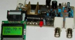
Supply voltage: 11-13.8 V (stabilized or from a battery)
Supply current: up to 1.2 A
Standard frequency range: 87.5-107.9 MHz
Audio / MPX input sensitivity: 2 V pp (for 75 kHz deviation freq.)
RDS / SCA input sensitivity: 0.2 V pp (for 7.5 kHz deviation freq.)
Board dimensions: 109 x 54 mm
Source: pira.cz PLL FM Transmitter pic assembly code schematic pcb alternative link:
FILE DOWNLOAD LINK LIST ( in TXT format ): LINKS-3188.zip
Source: TSA5511 5W PLL FM TRANSMITTER PIC16F627A
About The Author
Muhammad Bilal
I am a highly skilled and motivated individual with a Master's degree in Computer Science. I have extensive experience in technical writing and a deep understanding of SEO practices.