Description
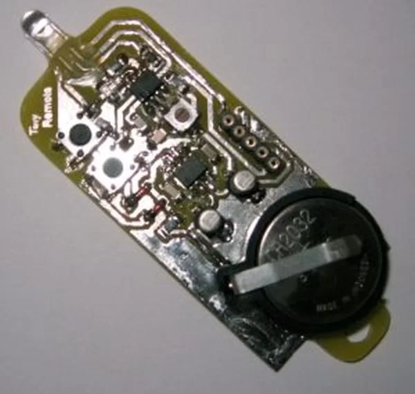
The Tiny Remoteis a very compact infrared remote control with only two buttons to control an iRobot Roomba. It produces three different infrared control signals that the robot interprets as Clean, Spot and Virtual Wall/Lighthouse.
The circuit is built mostly using SMD components to reduce its size, nearly to the size of a keychain and is powered by a CR2032 coin battery.
Design Considerations
After having designed the virtual wall, I wanted to be able to remotely control the robot. Most of the work had already been done on the assembler software of Virtual Wallso I was left with the tasks of redesigning the power supply and add two buttons.
Power supply considerations:
- It should be powered by a CR2032, CR2025 coin battery or similar;
- Idle current consumption should be 0 (zero) because these batteries have small capacities;
- Ideally the circuit should only consume power from the battery when a button is pressed;
- A voltage step-up is needed because 3V are not enough to power the PIC and infrared LED.
Like the Virtual Wall, the infrared pattern generator:
The infrared patterns emitted by the remote control are a form of PWM, modulated with a carrier frequency around 38KHz~40KHz. Below is a picture of the lighthouse pattern captured using a TSOP1238 and an oscilloscope.
Transmitting commands on the remote:
- Button 1 sends the Spot command;
- Button 2 sends the Clean command;
- Both buttons simultaneously send the Virtual Wall/Lighthouse command;
- Keeping buttons down will repeat its command until they are released.
No Stop command is included in the remote because it’s not needed! Each command, Clean or Spot, act as start when the robot is stopped and stop when it’s already running.
Generating the infrared 38KHz~40KHz carrier frequency:
Using a PIC microcontroller it is possible to output the infrared pattern and generate the carrier frequency. Mixing is accomplished by connecting the LED between the PWM output and the carrier output.
A solution is to use the PIC’s master clock oscillator output to produce the carrier frequency. This is the solution proposed by the circuit below. The PIC clock runs at 160KHz (FOSC) using an RC oscillator and the carrier frequency is available on CLKOUT pin as FOSC/4, at 40KHz.
Schematic
From left to right we have the CR2032 3V coin battery, the power supply based on a MAX619 regulator, the microcontroller 12F629, two LEDs, one emitting visible light and an infrared one and two push buttons. Connected to the microcontroller’s pin 2 (CLKIN) are R1 and C6 that form the RC pair for the PIC oscillator. There’s also a 5 pin header to connect the programmer (an ICD2 or another compatible one). The two diodes D1 and D2 will drive the MAX619 ~SHDN when any button is pressed.
For more detail: Tiny Remote for iRobot Roomba using PIC12F629


