Introduction
When I first started in the field of robotics, electronics and sensors I had always wanted to make my own robotic arm. The idea of being able to make such an advanced idea come to life out of simple parts found around the house was mind boggling to me. So inspite of that, I set out to prove to myself it was possible.
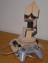
I went through several initial designs before I set my heart on the one that you see here. I feel this one is the simplest that I came up with and therefore the easiest to build. I still can’t get over the It’s made out of friggin’ wood! factor of this design.
 Purpose & Overview of this project
The goal of this project is to create a robotic arm that can move in most any direction like a humanoid arm. It should have grippers on the end that can grip trivial objects like a piece of paper or a pen/pencil. A simple design with as few moving parts as possible is important for this design because the arm will only be controlled by a PIC18F452. This potentially limits the ability to control the arm with smooth movements.
The Wooden Menace robotic arm should be made out of generally cheap household items (except the servos). The reason for this is to prove that such a design can and will work.
Wooden Menace with Controller
Parts List
- Electrical Parts
- LM7805 5 V Voltage Regulator
- PIC18F452 Microcontroller
- Female RJ45 Connector
- (5) Hi-Tec 311 Standard Servos
- 20 MHz Oscillator
- SPDT Switch
- 1µF Capacitor
- 30 pin SIP
- 540 point Breadboard
- Solder
- Wire 24 AWG
- Wire 30 AWG (aka Wirewrap)
- Hardware Parts
- Hobby Wood
- 8 small nails
- 5 minute E-poxy
- Fancy Door Hinge
- Plastic Sheet
- Tools
- Wirewrap Tool
- Soldering Iron
- Laptop Computer
- MPLAB IDE (installed on Laptop)
- PIC Programmer
- Power Drill
- Hammer
- Jigsaw
- Sand Paper
Schematic
Schematic Overview
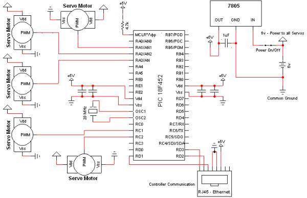
The hardware schematic for the wooden menace (robotic arm) is fairly straight forward. The PIC microcontroller has one control line feeding to each servo and it also connects to the RJ45 connecter. The RJ45 connector is used for getting input from the controller.
Schematic Specifics
- Power Circuit
- The power circuit is just a 9 V Battery hooked up to the LM7805 with a 1uF capacitor hooked to output & ground of the LM7805 to keep a steady 5 V DC.
- Servo Connections
- Each servo has 3 wires coming out of it. Power, Ground & Signal (PWM). Power & Ground are tied directly to our 6v source. Each signal pin from each servo is tied to a unique pin on the PIC as seen on the schematic.
- RJ45 Connector
- This project uses a [fake] ps1 controller to remotely control the robotic arm. The female RJ45 connector is used & mounted onto the robotic arm awaiting the male RJ45 connection from the controller.
- MCLR*/Vpp – Pin 1 on the PIC
- This is tied high (logic 1; +5 V) once again using a pull-up resistor. Pin 1 is effectively a reset pin. The PIC will restart-Memory Clear-when this pin is low (logic 0, +0 V). For this project I did not include a reset button so I just have the pin tied high always, so the PIC will always be running as long as it is powered.
Theory of Operation
Servo Theory
The picture to the right shows a simple PWM: Pulse with Modulation wave. Servos operate off of this principle.
The theory of how servos work is really quite simple. I’ll give a brief summary of it now, even though there will be a tutorial on servos fairly soon.
T = 20 mS
t = 0.9 S -> 2.1 S
If we put those values of t & T into the graph we will get a standard analog servo signal. It is important to note that t can vary while T is always the same. T which is 20 miliSeconds defines the period of the wave which also tells us that we are working at a frequency of 50 Hz
1 / 0.020 Seconds = 50 Hz
 The other portion of the wave that we want to understand is the t part. This is the ‘up’ part of the wave, meaning a positive +5 V is being given out. The rest of the 20 mS period a 0v should be output. The variance of 0.9 mS->2.1 mS is what tells the servo to move & where. Most servos can rotate 90° or 180° and the ones I use can rotate 180°.
So most simply put, we can tell the servos to move to a certain angle with great precision. Some examples for 180° seros….input: t, T and output: angle are seen below.
Hardware
The hardware design is just the cut out pieces of wood that form the base of the robotic arm & the arm itsself. It also includes the breadboarded circuit that allows the PIC control of the servos. We’ll take a ‘top down’ look at the Wooden Menace.
The Grippers
The grippers on the Wooden Menace robotic arm are attached using screws, pieces of wood cut with a jigsaw and small screw & nuts. This simple setup is surprisingly stable. The Hi-Tec 311 standard servos that are used offer enough power to grip a vast amount of objects.
For more detail: The Wooden Menace – a Mighty Robotic Arm Powered by Servos
About The Author
Ibrar Ayyub
I am an experienced technical writer holding a Master's degree in computer science from BZU Multan, Pakistan University. With a background spanning various industries, particularly in home automation and engineering, I have honed my skills in crafting clear and concise content. Proficient in leveraging infographics and diagrams, I strive to simplify complex concepts for readers. My strength lies in thorough research and presenting information in a structured and logical format.
Follow Us:LinkedinTwitter