
Design Goal:
The TechBot1 is a small line following robot designed for for the
1998 Embedded Systems conference in San Jose California. It was
built by Jerry Merrill and myself and was designed as a promotional
robot that would follow a black line drawn on a dry erase board.
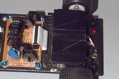
Motive Power:
The TechBot1 uses 2 Cirrus CS-70 servos that have been modified
for full rotation and have had their controller boards removed to
convert them from servos to gear motors.
Servos are a common motive power for small robots due to their
low cost, ready availability, standardized sizes and the fact that it
only requires 1 bit on your processor to control the motor.
We initially tried this approach but found that the speed control was
very minimal with a finer control needed for this application. The
servo controller boards were then removed and the wires soldered
to the motor terminals and case ground. The motors were then
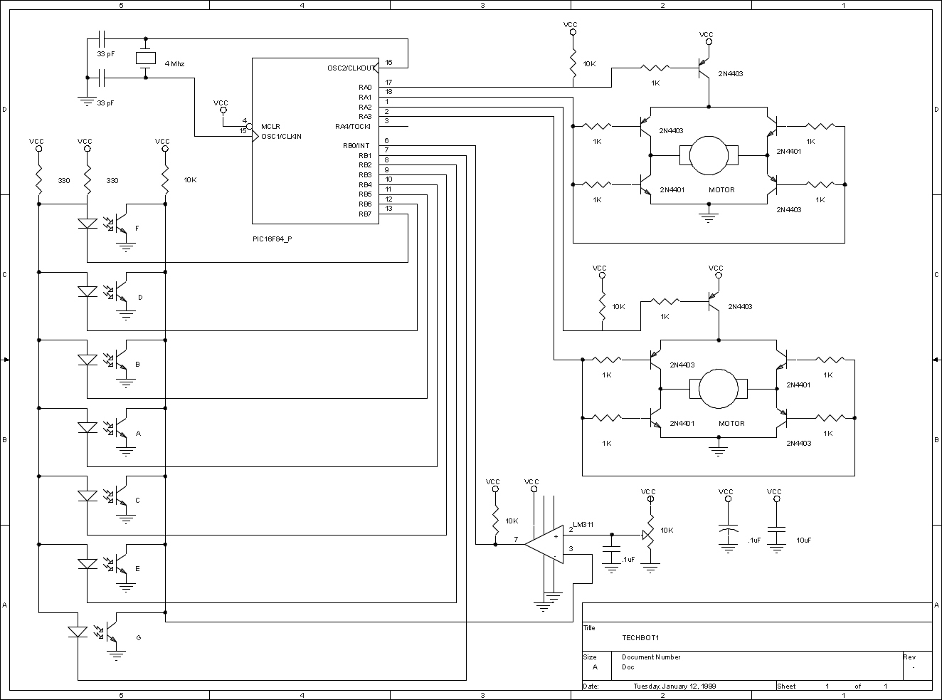
controlled by an H-bridge circuit to allow direction and speed control
with only 2 processor bits per motor. Initially a 4 transistor Bridge was
used but during power up the transistors would turn partially on and
start conducting. This was corrected by adding a 5th transistor to the
top of the H-bridge to control motor power. This also simplified the
software into having one bit for direction and another bit for
power/speed control per motor.
Sensors:
In order to follow the line I/R reflective sensors were used to
detect if a line was present or not. The sensors chosen are the
QRB1114 from QT Optoelectronics and have a focal point of
about 1/4 inch. They are available from DIGI-KEY.
Most line followers use 2 or 3 sensors of this type to do their
detection. This works but does not give the ability to follow
lines with very tight turns. We used an array of seven sensors
arranged in an “inverted V ” arrangement placed
under the front of the robot behind the skid wheel. The sensors
are wired with all the receivers connected in parallel and fed to
an LM311 comparator to set the threshold trigger level with it’s
output fed to a processor bit. Each transmitter LED is connected
through a current limiting resistor to a processor bit. This allows
the entire array to use 8 bits for the sensors.
For more detail: TechBot line following robot using PIC16F84
About The Author
Ibrar Ayyub
I am an experienced technical writer holding a Master's degree in computer science from BZU Multan, Pakistan University. With a background spanning various industries, particularly in home automation and engineering, I have honed my skills in crafting clear and concise content. Proficient in leveraging infographics and diagrams, I strive to simplify complex concepts for readers. My strength lies in thorough research and presenting information in a structured and logical format.
Follow Us:LinkedinTwitter