I got to the result so it requires a bit more reading.
At home we have quite some electronic tea lights, the ones from Philips that can be charged wirelessly. I have made an Instructable before related to this topic, see Tea Light Charge Monitorr.

After some time these tea lights stop working because the rechargeable battery goes bad. There are two options to address this problem:
- You throw the tea light away and buy a new one
- You replace the rechargeable battery
I tried the second option. The video in the last step of this Instructable shows how you can do that. That video also shows how Philips redesigned these tea lights over the years making them cheaper to produce but unfortunately lowering the life span of those tea lights. Next to that I noticed that with the latest cheaper designs it is hard to switch the tea light on and off. It uses as tilt switch for that but apparently they do not always seem to work very well.
When I replaced the rechargeable battery for the first time, the tea light did not work. I began to think that maybe the tea light keeps some kind of counter to see how often it is used and then never switches on again. That was the reason for starting this project since I wanted a tea light that would work forever, of course replacing the rechargeable battery once and a while.
I must admit that my bad thoughts were wrong, once you have replaced the battery – even when they are charged – you need to put the tea light in a charger very shortly to make it work again. I do not know why that is but it needs to be done to get the tea light started.
Anyway, I had already started making my own tea light which would behave the same as the Philips tea light. I analyzed the electronics and the pattern Philips is using to create the nice candle effect. The original electronics were a bit more complex than I expected so I decided to make my own simpler design. I was able to figure out the pattern for the candle effect by analyzing the pattern on an oscilloscope. Some screenshots of a part of this pattern are added. A low signal means that the led is on.
As said my design became simpler than the Philips design and it does what it needs to do. I re-used the housing, the leds, the tilt switch and the coil from a tea light that did no longer work and created my own version with a PIC12F615 using the JAL programming language to control the device.
Step 1: Analyzing the Original Tea Light
Before the clone could be made I needed to figure out how the original tea light worked but I could only figure it out partly because it was more complex than I initially thought.
Measurements revealed the following:
- The candle pattern is pseudo random since it is repeated after a while where only the top led of the two leds changes brightness. The bottom led is continuously on. See the video on how this works
- The tea light uses two high brightness leds using a current of about 7 mA per led
- The device switches itself off when the battery voltage drops below 2.1 Volt
- Depending on the design (see the video in the last step of this Instructable) the NiMH battery gets charged with a current varying from 11 mA to 37 mA
Step 2: Designing the Clone
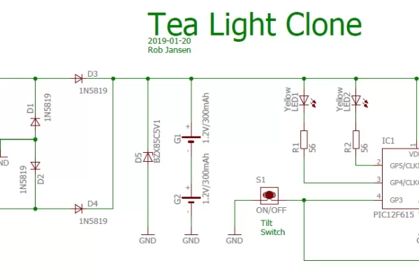
In the schematic diagram you see how I designed the clone. The following parts can be distinguished:
- The rectifier bridge using four 1N5818 Schottky diodes. The reason for using these type of diodes is because of the low voltage drop. This bridge converts the AC voltage from the coil to a DC voltage for the device.
- Capacitor C1. It does not seem to be important but this capacitor brings the charging coil into resonance resulting in a high voltage swing. Without this capacitor the coil would not generate enough power for the device. In the two screenshots from the oscilloscope you see the coil output voltage when it is placed in a charger without (single peak) and with (sinus signal) the capacitor.
- Zener diode D5 with a value of 5V1 seems a bit strange in this de design since the supply voltage does not get higher than around 2.5 V because of the two NiMH batteries. However, if these batteries are becoming end of life, their voltage increases and the peaks in the voltage from the charging coil will become higher than the maximum voltage the PIC can handle – which if 5.5V – so the Zener cuts of these peaks, protecting the PIC in that situation.
- The tilt switch is connected to the interrupt pin of the PIC. This guarantees that the PIC will wake up after it has been powered down.
- The PIC controls the two leds directly from two of its ports.
In this design the charge current of the batteries is about 17 mA when placed in the wireless charger. The batteries have a capacity of 300 mAh. This type of battery is fully charged when charged for 14 hours with a current of 1/10 of the capacity, so in this case 30 mA. This means that the device will never be fully charged unless it is charged twice. In the video about changing the battery at the end of this Instructable you also see that Philips uses rechargeable batteries with a capacity of 160 mAh in their lastest designs.
In the video you can see the operation of the original tea light and the clone. Do you see which one is the original and which one is the clone?
Step 3: Required Components and Building the Clone
You need to have the following components for this project:
- A piece of breadboard
- PIC microcontroller 12F615
- 8-pin IC socket
- Diodes: 4 * 1N5819, 1 * BZX85C5V1
- 2 * 100nF ceramic capacitors
- Resistors: 1 * 1MOhm, 2 * 56 Ohm
- 2 * 3 mm high bright led (from an old tea light)
- Tilt switch (from an old tea light)
- Charge coil from an old tea light
- Housing from an old tea light
See the schematic diagram in the previous section on how to connect the components.
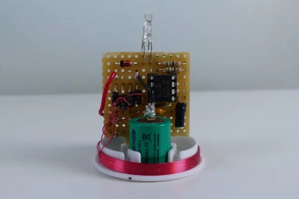
Since the design is not using any SMD components, it needs more space than the original version. Because of that the breadboard was cut in such a way that it has more space on the sides. This only works if you have a high tea light. There are also smaller version (see the video in the last step of this Instructable) but the design will not fit unless you build it with SMD components.
In the pictures you see how the device was build. Note that the top led is mounted on the solder side of the breadboard as to be able to put it on top of the other led.
Step 4: The Software
As already mentioned, the software is written for a PIC12F615 using the JAL programming language.
Initially the PIC will be in sleep mode when powered on for the first time, consuming hardly any power in that state.
The software performs the following tasks:
- When the device is turned upside down, the tilt switch will make contact with ground which will wake up the PIC from sleep.
- Once awake the bottom led will be switched on and the top led will use the cloned Philips candle pattern to change the brightness of the led.
- During operation the PIC will measure the supply voltage using its on-board Analog to Digital Converter (ADC). When this voltage drops below 2.1V, it will switch the leds off and will put the PIC in sleep mode. The PIC could still operate well at 2.1 V but it is not good for the rechargeable batteries to be completely drained.
There is a difference in how the original tea light behaves compared to the clone. When the battery voltage drops below 2.1 V the original tea light will not start until the device is charged again so it seems it measures the supply voltage at power up. The clone, however, will measure the supply voltage after it is active. This means that when the supply voltage is below 2.1 V the leds will work for a short time after which it the device goes to sleep again.
There is one remaining point that I did not figure out. When the batteries turn bad, the original tea light will no longer switch on even when the supply voltage of the battery is sufficient (the reason for my initial bad thoughts about the device, remember?). Maybe it remembers that the batteries have gone bad by having measured a high battery voltage. In the clone, this is not done. Even if the batteries have gone bad and the supply voltage gets high – protected by the Zener diode – the device will work but because of the bad battery the operation time gets shorter.
The JAL source file and the Intel Hex file for programming the PIC are attached. If you are interested in using the PIC microcontroller with JAL – a Pascal like programming language – visit the JAL website.
Attachments
Step 5: Replacing the Rechargeable Batteries
If you do not want to build the clone but only want to replace the battery have a look at this video. It also shows how the original tea light design got simplified resulting in unfortunately a product that has a shorter life time.
As mentioned earlier, the latest simple design seems to have another problem since these tea light are very hard to switch on an off. Initially I thought it was because of a bad tilt switch but having re-used this switch in the clone it all worked fine. So cloning may be a good option after all.
Have fun building your own project and looking forward to your reactions.
Source: Tea Light Clone
About The Author
Muhammad Bilal
I am a highly skilled and motivated individual with a Master's degree in Computer Science. I have extensive experience in technical writing and a deep understanding of SEO practices.