analog

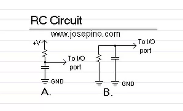
RC Circuit

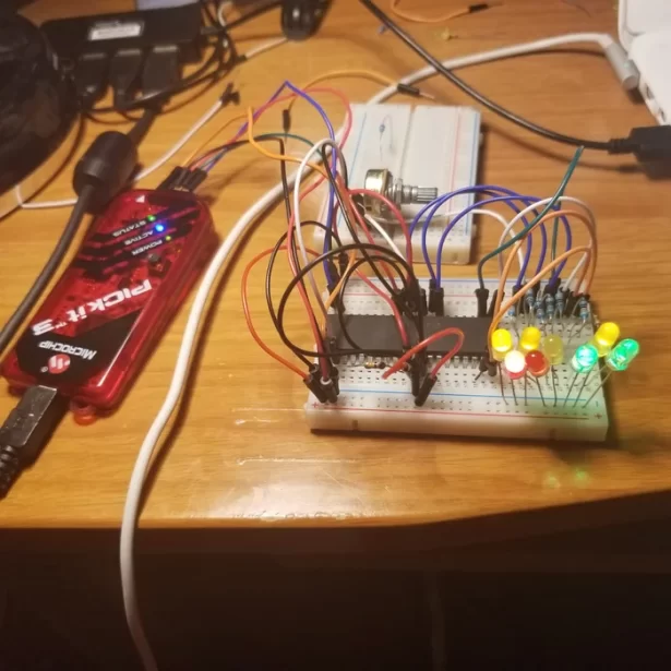
Read analog values without an ADC using PIC12F675 microcontroller

Digital electronics and Analog electronics doesn’t mix easily. A Microcontroller can’t get analog values unless an Analog-to-Digital converter is used, however, you may find a little complicated the use of an ADC and it need lots of Input/Output ports.   Some Microcontrollers, like the small 8-pin Microchip PIC 12F675, do have an ADC integrated, but …

Read analog values without an ADC using PIC12F675 microcontroller Continue Reading

Analog to Digital Converter Using PIC16f877A Microcontroller

Analog to Digital Converter Using PIC16f877A Microcontroller – Beginners Guide using pic microcontoller

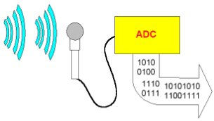
What is meant by Analog to Digital Converter (ADC)? An ADC converts analog signal to it’s corresponding digital signal. How to convert analog signal to digital signal? CircuitsGallery.com has already posted ADC using LM324 IC, in that ADC tutorial I had already explained Analog to Digital Converter how it works. While dealing with Microcontrollers we may …

Analog to Digital Converter Using PIC16f877A Microcontroller – Beginners Guide using pic microcontoller Continue Reading

CONTROL OF 8 SERVOS MOTOR

PIC16F876 CONTROL OF 8 SERVOS MOTOR 5 ANALOG CHANNELS I2C BUS

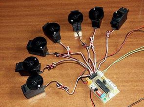
Microcontroller PIC16F876 4Mhz Controlled by the I2C slave module and analog servos technical report describes the design, both from the electronic point of view, as a computer control board for I2C bus 8 standard… Electronics Projects, PIC16F876 Control of 8 Servos Motor 5 Analog Channels I2C bus”microchip projects, microcontroller projects, pic assembly example, pic16f876 projects, “ Microcontroller PIC16F876 4Mhz Controlled …

PIC16F876 CONTROL OF 8 SERVOS MOTOR 5 ANALOG CHANNELS I2C BUS Continue Reading

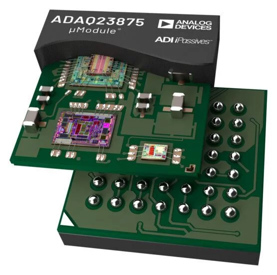
ANALOG DEVICES’ TINY ΜMODULE BOOST REGULATOR FOR LOW VOLTAGE OPTICAL SYSTEMS

ANALOG DEVICES’ TINY ΜMODULE BOOST REGULATOR FOR LOW VOLTAGE OPTICAL SYSTEMS

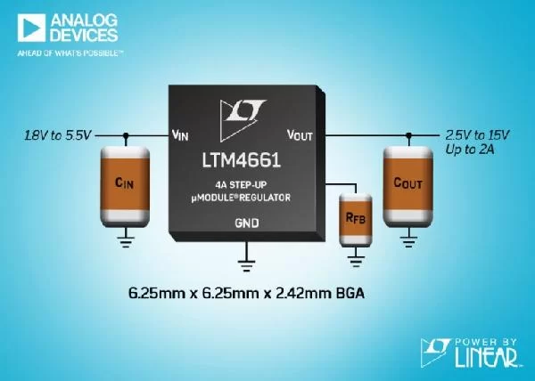
Analog Devices, Inc. has announced the Power by Linear LTM4661, a low power step-up µModule regulator in a 6.25mm x 6.25mm x 2.42mm BGA package. Only a few capacitors and one resistor are required to complete the design, and the solution occupies less than 1cm²single-sided or 0.5cm²on double-sided PCBs. The LTM4661 incorporates a switching DC/DC controller, …

ANALOG DEVICES’ TINY ΜMODULE BOOST REGULATOR FOR LOW VOLTAGE OPTICAL SYSTEMS Continue Reading

Fastest 18-Bit SAR ADC unveiled

Fastest 18-Bit SAR ADC unveiled

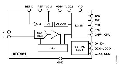
The AD7960 is an 18-bit, 5 MSPS charge redistribution successive approximation (SAR), analog-to-digital converter (ADC). The SAR architecture allows unmatched performance both in noise and in linearity. The AD7960 contains a low power, high speed, 18-bit sampling ADC, an internal conversion clock and an internal reference buffer. On the CNV± edge, the AD7960 samples the …

Fastest 18-Bit SAR ADC unveiled Continue Reading

PIC16F1787

New Intelligent Analog Solutions – Enabling Efficient Lighting, Motor Control and Power Conversion – PIC 16F1787

Features Enhanced Mid-Range Core with 49 Instruction, 16 Stack Levels Flash Program Memory with self read/write capability 256 Bytes of EEPROM Internal 32MHz oscillator 3 x PSMC (Programmable Switch Mode Controller)- Dedicated 16bit PWM- Digital and/or analog feedback control of PWM frequency- Dead-band control / auto-shutdown & restart 4 x Fast Comparators with selectable Voltage …

New Intelligent Analog Solutions – Enabling Efficient Lighting, Motor Control and Power Conversion – PIC 16F1787 Continue Reading

How-to use PWM to Generate Analog (or Analogue) Voltage in Digital Circuits

Many times, designers are faced with the need of generating analogue or analog voltage levels in purely digital circuits. Although the market provides today a very broad range of dedicated digital-to-analogue converters, putting such a device in the schematic has a negative impact on the overall cost of the system. 1. Introduction In the first …

How-to use PWM to Generate Analog (or Analogue) Voltage in Digital Circuits Continue Reading

Analog to digital 8 bits For CSS Compiler

  #include <16F877.h> #device adc=8 #FUSES NOWDT ,XT #use delay(clock=4000000) #include <Lcd_4bit.c> int8 value; void main() { setup_adc_ports(AN0_AN1_AN3); setup_adc(ADC_CLOCK_DIV_2); setup_psp(PSP_DISABLED); setup_spi(SPI_SS_DISABLED); setup_timer_0(RTCC_INTERNAL|RTCC_DIV_1); setup_timer_1(T1_DISABLED); setup_timer_2(T2_DISABLED,0,1); set_adc_channel(0); set_tris_d(0x00); set_tris_A(0xff); Lcd_init(); while(true){ set_adc_channel(0); delay_ms(10); value = read_adc(); // 0-1023 Lcd_row_col(1,0); Lcd_putc(“setpoint=”); hex_bcd(value);lcd_row_col(1,9);sent_Lcd(); delay_ms(50); } }