
Hi all! Here’s the new project where I’m working a couple of days. Since I develop the SIM900 module and test it, I don’t work with it. Also, I’ve got at home some samples of the MCP2200 USB bridge that I want to test it. So make an USB interface for this board was the perfect idea! This allows to use the SIM900 board with a PC, Raspberry or similar, with the plus of no need external power supply or control signals. Just plug the USB cable on the board and start communicating with the world!
- The Hardware
To develop this board, again I use element’s I’ve got at home. First of all, the scheme, that you can download here: SIM900_USB_CONTROLLER. This is the USB interface, you may also want the scheme of the SIM900 module, to have a global vision of both boards. All the info of this module is here.
The scheme shows the required hardware for the USB interface. It’s really simple, and has the following parts:
- USB connector: Type B, right angle. The easiest connector to solder in the breadboard.
- 5V / 3V3 LDO: The SIM900 interface works with 3V3 levels, so the USB brigde must comply with this. For this reason, I include the MC33269 LDO, so with the 5V from the USB port I can power all the USB stage with 3V3. Note that the internal reference VUSB pin on the MCP2200 is connected to this 3V3 power supply. With this configuration, the internal LDO of the MCP2200 is disabled. Also, another consequence is that the ‘1’ logical level on the GPIO pins will be at the 3.3V level.
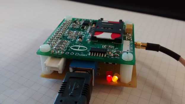
- MCP2200 Usb bridge: An easy way to have a bridge between USB and a serial port. This chip is a 18F14K50 PIC micrcontroller with a custom firmware, you can read here about it. I’ve got a couple of samples at home in 20-pin SO format, so with the help of an adapter like this one, it’s very easy to include in any design. Also, people at Dangerous Prototypes develop a breakout board that I used as inspiration. About the circuit, nothing special: it requires an external 12MHz crystal and a pull-up resistor in the pin 4 (RST). I also use pins 5 and 6 to signaling the activity on the serial port with two led’s. It’s really easy to use.
- SIM900 Board connection: The interface with the SIM900 board I develop previously. To power this board, I use the 5V from the USB port. And TX / RX signals to control the modem, nothing more.
For more detail: SIM900 USB Communication using MCP2200
About The Author
Ibrar Ayyub
I am an experienced technical writer holding a Master's degree in computer science from BZU Multan, Pakistan University. With a background spanning various industries, particularly in home automation and engineering, I have honed my skills in crafting clear and concise content. Proficient in leveraging infographics and diagrams, I strive to simplify complex concepts for readers. My strength lies in thorough research and presenting information in a structured and logical format.
Follow Us:LinkedinTwitter