Background
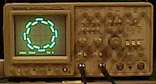
My friend Arthur, in his lifelong quest for circuits that don’t really do anything useful, but are really neat nonetheless, built a really neat Lissajous pattern generator. This Lissajous pattern is not your traditional circle, oval, or figure-8, it is a circle with varying amplitude, in a pattern that makes it look like a sprocket. Not satisfied with that, he also made it so that the sprocket rotates.
An interesting side-effect is that this circuit very clearly shows some of the shortcomings of digital oscilloscopes. Whenever an oscilloscope salesman comes around, he whips out this box with a switch and 2 BNC jacks. It has been known to render speechless the best salesmen from HP and Tektronix. They usually dismiss it as a toy, but I think that is just because they have to follow the party line: Analog scopes are dead. I have seen a digital scope or two accurately mimic the analog, most notably the Digital Phosphor scopes from Tektronix, but in general, the RSWG breaks digital scopes.
I moved to another job about 1500 miles away from where Art spends his time being surly, making cool circuits and serenading passersby with his Theremins. After a short time at my new lab I was called upon to specify some oscilloscopes. I decided that I needed my own RSWG. Arthur has been so kind as to publish theschematics and theory behind his RSWG. His circuit works great, but it is pretty complex, and the construction would tax my patience, since he has managed to construct his RSWG with nothing but discrete ICs and a handful of ancillary components.
I, on the other hand, like most engineers, decided I would rather start from the ground up and roll my own. My first objective is to reduce parts count. When I was working for the Army, I made a really neat circuit that was among other things, a frequency synthesizer. It would generate two sine-waves in quadrature with a minimum of external components (just a D/A converter). The problem with re-using that code was that I no longer had easy access to an Altera development system. On the other hand, I had been using a PICStart+ for some of my other projects at the lab, and if all else fails, I would have the POHPIC Programmer that I designed myself. I decided to try basing it on a MicrochipPIC, the 16F84. The ‘F84 has some features that are completely unnecessary for this project, notably non-volatile memory. But the big advantage of it is that 1) I had some handy, and 2) the flash program memory supports my style of simulate, burn, crash, repeat embedded programming, without the hassle of an EPROM eraser. This code would easily port over to one of the PICs without flash memory (such as the 16C61).
The Circle
First of all, I had to see if I could even draw a simple circle on the oscilloscope screen. To do this, you must put out 2 sine waves in quadrature (a fancy term for 90° out of phase). When you feed these two waves into the X and Y inputs of an oscilloscope, you draw a circle on the oscilloscope’s screen.
A sine wave is about as analog a signal as you can get. In case you didn’t realize it, the ‘F84 only has digital outputs, so I needed to convert a digital set of values to an analog voltage. I could use a D/A converter, but I didn’t have any handy. What I did have handy was a huge number of precision resistors. Just the recipie for an R/2R resistor ladder, which is what you see to the left. To use an R/2R D/A network, you place the digital word you want to convert to an analog voltage on the input pins. The closer the 1s are to your supply voltage, and the 0s are to ground, the better, since these voltages are added together through these resistor dividers to generate the analog voltage. The most significant bit goes on the upper-most input of the diagram to the left, and the least significant bit goes into the bottom-most input.
The 16F84 has 13 outputs. All 13 can serve as inputs, but only 12 are normal outputs, one is an open-drain. An open-drain output has no active pull up- you have to provide an external (passive) pull up. Since the ‘F84 is CMOS based, this leaves us 12 outputs that have good, low impedance 1’s or 0’s. We want two channels, 12/2 = 6 bits/channel. Using the rough approximation of 6 dB/bit, 6 bits/channel * 6 dB/bit gives us approximately 36 dB/channel of dynamic range. This is still very visible on a scope, so I needed some filtering.
For more detail: Rotating Sprocket Wheel Generator using PIC16F84


