
Introduction
Many embedded systems leverage a hierarchical structure in their product architecture for a more robust and efficient product. The more complex the product becomes, it is more preferable to segment tasks according to the processing unit’s role to observe optimal tradeoffs in the system. For instance, it would be impractical for a single processing unit to handle both user interface tasks while also handling real-time control tasks. User interface tasks are very tolerating to missed deadlines while the latter is not. Rather than having a single processing unit that can comprehensively handle both ends of the spectrum, such as real-time operating systems (RTOS), this project explores a more modular build by segmenting high-level and low-level tasks to separate processing units in order to implement a complex system like a vision-driven robotic arm.
The Robotic Candy Sorter is an interdisciplinary project that integrates mechanical, electrical, and software aspects. The report discusses the inverse kinematics involved in mapping servo angles to orthogonal spatial coordinates, the individual electrical systems, and the software that handles object recognition to drive the FSM. The segmentation of the processors’ roles in this project aligns well with our academic purposes as well. The RPi development of the project was done for Cornell University’s ECE 5725 Embedded OS course and the PIC32 development of the project was done for ECE 4760 Microcontrollers courses.
System Overview
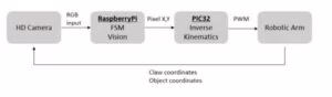
The high-level task processing unit is the Raspberry Pi Model 2 B+ with a 900 MHz quad-core 32-bit ARM Cortex A7 CPU. The low-level task processing unit is the Microchip PIC32MX250F128B with a 40 MHz MIPS M4K 32-bit core and 5 stage pipeline. The communication between the two processors is handled by a UART serial interface. To summarize the software of the project, the robotic arm has a vision-based control. Rather than precisely mapping camera pixel coordinates to robot x,y,z coordinates, the software uses an adaptive control scheme where processing each frame yields an incremental movement of the arm. The vision software uses the OpenCV and PySerial libraries to processes commands and send them to the PIC32. The PIC32 receives commands, solves the inverse kinematics and then outputs the new angles to each of the servos on the arm. The arm was built from the popular MeArm design.
Standards
For our final project, no standards were required to be followed.
Copyrights
We did use some existing code when constructing our project. This is mentioned below as needed and all atribution is given in the References section.
Hardware Implementation
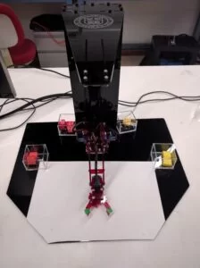
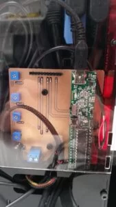
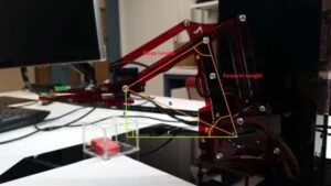
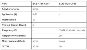
A lot of work went into designing the hardware to meet the requirements of the class. We were required to maintain a budget of under $100 and complete the project in five weeks. To do this we decided to use prebuilt systems whenever possible. We found that the MeArm 1.0 design met all of our requirements without breaking our budget. The 3mm acrylic for the arm and base was salvaged from the scrap pile at Cornell’s Rapid Prototyping Lab and all of the bolts, nuts and servos were collected from the leftovers of past projects of the Cornell Maker Lab. Additionally, the PCB mill in the Maker Lab was used to manufacture the printed circuit board.
The major flaw that needed to be fixed with the MeArm design was the instability of the base. The original design left a large gap between the fixed base and the rotating piece. This meant that whenever the arm would move there would be additional deflection caused by the gap. To fix this instability, we designed a two piece spacer system that is inserted in the base to prevent it from tipping when the arm extends. This greatly improved the rigidity of the whole arm and made testing much easier as all of the moves were repeatable now.
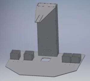
The goal of the base design was to protect and display the electronics while also allowing us to mount the camera. The base uses a jig-saw and t-nut pattern to allow the acrylic pieces to be assembled with minimal effort. This also produces a very rigid column which was needed to support the cantilevered camera mount. All of the CAD was done in Autodesk Inventor and then the drawings were exported as PDFs so that they could be laser cut.
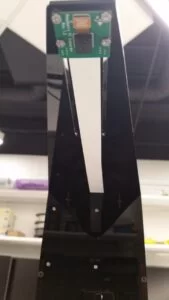
The design of the camera mount was the hardest part of the mechanical design. We wanted to have a system that had flexible mounting options so that we could adjust the camera to get the perfect angle and maximize field of view. We ended up mounting the camera in parallel slots so that it could be moved in and out to adjust the center of the image. Additionally, spacers were inserted under the camera to cancel out the tilt caused by the deflection of the cantilever. Finally, the electronics tower was made slightly taller than it needed to be so that we had room to adjust the range of the image.
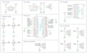
The design of the PCB was very simple as it only needs to breakout the connections and distribute power. Since the PIC32 runs off of 3.3V, a high power 5V source was needed for the servos. This was done by using an external DC power supply and running out a 2.1 mm barrel jack to hookup the power. Additionally, breakouts were made for the LCD, serial UART and PWM outputs. Finally, four potentiometers were included to give us the ability to control the arm without a computer. All of the electronics and hardware were assembled with no problem and we were able to quickly transition to writing the software.
Software Implementation
The RPi allows for GPIO peripheral ports as well as the ease of development on Linux operating system. As a result, RPi handles the high-level sequence of execution code as well as the integration with the PiCamera for image processing. Once the image processing section of the FSM is completed, the RPi calls the sort function that detects position of the object and requests a sequence of arm movements to the PIC32 via the serial port. The goal of this sequence is to posistion the claw above the candy, grab it, and then sort it. This structure demonstrates the high level of abstraction of the RPi because the motor control commands are abstracted by PIC32, and the RPi can proceed to the next stage of the FSM.
FSM on the Raspberry Pi
The Finite State Machine is what is executed in the main loop of the python script for the Robotic Candy Sorter. The FSM has 5 different states: IDLE, INIT, DETECT, MOVE TO, MOVE OBJECT. The execution and transition between states is summarized in the illustration below.
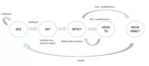
In the IDLE state, the script waits for user input on the terminal. If the character input matches to the list of provided sortable colors, the FSM advances to the INIT state. In the INIT state, an instance of robot arm class is created and the serial interface is started. In addition, one frame of input image is processed to create a list of candy objects that are in the visible sorting field. Each candy object has a variable of color, position, and isSorted boolean to facilitate the sorting and tracking procedure.
The DETECT state is where the image processing is done to updated the position of the claw as it moves. To make the control robust to outlier or a dropped frame, we implemented a median filter of size 5 for the detected position. It leverages the history of positions from the past 5 frames to make the control scheme more robust. If the euclidian distance from the claw and targeted object is less than specified distance of 10 pixels (about 1 mm), the FSM transitions to the MOVE OBJECT state. However, if the distance is greater than the desired radius, the FSM transitions to the MOVE TO state, where the arm will take an incremental step to reduce the distance. Finally, once the arm has taken sufficient incremental steps to the targeted object, the FSM will transition to the MOVE OBJECT state, in which the robot will execute sequence of predefined movements to close the claw, pick up the candy, go to the sort basket, drop the candy, and return back to home position. Once completed, the FSM returns back to the IDLE state where the user can input another request of sort.
Object Detection on Raspberry Pi
The object detection algorithm uses the Python OpenCV library on the RPi. The PiCamera library is also used to import the 5 MB RGB picamera input to a numpy 2D array. Once the RGB frame from the PiCamera is captured into a matrix format, image operations from OpenCV were used to recognize the candy and claw colors. The image processing pipeline used is shown below.
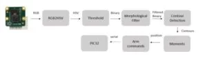
We first process the convert RGB input into the HSV color scheme. Operating in HSV provides significant benefits over RGB since isolating the desired color is as simple as comparing the hues. By bounding the upper and lower hue limits of a desired color value, we can extract the candies. HSV also provides better robustness to fluctuation in lighting condition since the hue captures the apparent color irrespective of saturation or value. The next matrix operation thresholds the colors to form a binary matrix of the pixels detected to be the desired colored candies. An identical operation sequence is used to detect the claw position.
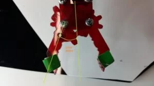
To determine the position of the claw, we tagged the tips of the claw with green markers. The position of the claw is then determined by finding the centers of the two green objects and finding the midpoint of the line between them. The claw position is only updated when both contours of the green object is captured.
The binary outputs corresponding to the claw and candy pixels are then de-noised with a morphological filter that erodes and dilates the binary matrix. The morphological filter resulted in better contour detection over alternative filtering schemes tried such as a traditional median or Gaussian filter with a 5×5 kernal. This is because the resulting binary matrix from eroding and dilating function maintains the edge while also filling in the non-connected values in the surrounding body.
The greatest benefit of using the OpenCV library is the provided contour detect function. With the given input of a binary matrix, the contour detect function gives a list of object boundaries. This list contains spurious detected objects from remaining noise and even sometimes duplicate regions of one candy. To prevent these cases, we filter out contours by size and shape. If the detected contour is less than a specified pixel area, then it is not determined to be a candy. In addition, because the candies have a regular ratio between width and height, we can further filter our contours to only detect instances that are of the desired shape.
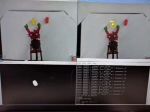
To facilitate debugging and development, we overlay the detected contour and its center of mass onto the raw RGB capture frame. In addition, we print out messages onto the terminal to see what the program is doing. As shown in the figure, the terminal output captures the current state, the detected delta X and delat Y positions between the candy and the claw, and the euclidian error distance.
Serial Communication
As mentioned above, the PySerial library was used to send and receive data from the RPi to the PIC32. A command language was developed to standardize how the data was sent. Each command is in the format of a character command letter and a float value. There are options to set the absolute cartesian and cylindrical coordinates or to take steps in any direction. A python module was written to abstract this language to a set of function calls that can be used to initialize and control the arm.
PIC32 Code
To begin discussing the PIC32 Code we must first define how each joint angle is defined and then go over how this is transformed into cylindrical coordinates with inverse kinematics. Since the arm has 3 DOF and a claw actuator, their are four joints to consider: the base, the shoulder, the elbow, and the claw. The goal of inverse kinematics is then to take an input cylindrical coordinate (theta, r, z, claw) and determine what joint angles would get the arm there. Cartesian input coordinates are first transformed into cylindrical in the standard way.
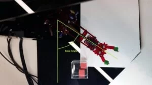
Looking from above, the base angle is just the internal angle formed by the arm and the line extending from the center to the right. If we let this line become the x-axis, then the base angle is simply the desired theta coordinate. The claw angle is defined in a similar way, it is the internal angle between the center of the claw and gripper position.
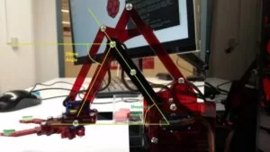
The final two joints, the shoulder and the elbow were the most difficult as simultaneous movements are required to produce the last two coordinates: r and z. The inverse kinematics is performed by solving the triangle formed by the forearm, bicep and the line formed by the desired r and z coordinates. Then, by the law of cosines and more trigonometry, each joint angle is solved. With the shoulder angle being the angle of elevation of the bicep and the horizontal plane, and the elbow angle being the angle of declination between the forearm and the horizontal plane. This math produced a set of equations that were converted into efficient c code to be ran on the arm.
Code execution begins in the main function which makes calls to initialize and start the thread scheduler. To keep the code short it was decided that the code needed to be separated into modules. The first of which is types.h which houses all of the structs to package all of the joint and servo values into one variable. Additionally, scaling.h and scaling.c were written to hold helper functions that convert and map coordinate systems. The user input is handled in the parse.h and parse.c files. It is their job to have a function handler for each command character that first verifies the validity of the command value in the range and then set the appropriate input value. To know what the limits of the arm were, limits.h and limits.c were written to house the macro constants and functions for testing whether the move was in bounds. If the move was inbounds, the calculation thread calls the solve function in ik.h and ik.c to get the output servo angles. The output thread then uses arm.h and arm.c to first convert the angles to PWM values using the calibration data in calibration.h and then write the PWM data to the motors.
The main advantage of the modular design was that each module could be fully written and tested before moving onto the next part and that the code was easily written as threads. There were three threads used, the command thread to take user input, the calculation thread to process it and the output thread to send the results to the servos. The modules became very useful when working with the inverse kinematics as it allowed us to verify that the math worked and that the arm would not attempt to destroy itself. To protect the arm, conservative limits were placed on the ranges of each coordinates. This limited what the arm could do, but was not a problem in our setup.
Testing
Throughout the development of the project, we leveraged a modular functionality, incremental development, and test-driven approach. Given the extensive amount of mechanical, electrical, and software required to integrate the robotic arm, we initially defined the design components, the high-level requirements within each component, and the dependencies between the subsystems. This approach allowed us to highly parallelize the development process. For instance, the vision and FSM code on the Raspberry Pi was developed in parallel with the motor control on the PIC32.
The precision of the robotic arm movement was a challenging aspect of this project. To overcome this hurdle, we introduced a vision-based corrective control so that the system could use visual feedback to correct its path to the target. Finally, the color thresholding range for the vision as well as the material of object to sort had to be tested across various options.
We initially started with Skittles as our candies to sort because they tasty, but introduced they have a mechanical complexity due to their small, slippery, round surface. We resorted to an easier sorting candy of a Starburst with more rigidity and bigger size, but less favorable colors to detect.
Safety
We put a lot of thought into safety, to protect our project and ourselves. The base is designed so that with the software limits the arm cannot reach outside of it or collide with itself. Additionally, since the acrylic that we used was not FDA aproved for food handling or storage we did not eat the candy after the arm touched it. Finally, we enclosed are electronics and used UL listed power supplies to prevent shorting and fire hazards.
Usability
A lot of focus was put into making the arm easy to demo and use. All of the code on the PIC32 starts up automatically and then any terminal program can be used to communicate with it. All of the code on the Raspberry Pi starts from a shell script so that important steps are not done out of order or missed. Additionally, all of the electronics and wires are enclosed and sleaved to prevent damage and user repairs. We believe that these systems are simple enough that anyone who could use a computer could use our project.
While our project does not tackle a big issue or fix a major life problem we believe that it still has merit. It is an interesting and fun introduction into robotics and computer vision and will be repurposed as an attractive display to inspire the next generation of engineers.
Interference with Other Designs
All of our software and hardware is self contained and we know that it poses no harm to other designs or people.
Results and Conclusions
We were successfully able to implement a vision-based Robotic Candy Sorter. The user could provide desired input color between red and yellow, and the robotic arm would correctly locate the correct candy and sort it. We observed high consistency of correct color and position detection with our vision system. Under fixed lighting environment, the camera would reliably detect the target candy. In the case that a single frame couldn’t detect the target, the median filter of the previous 5 target positions would act as a buffer to ensure the robot arm has constant trajectory to follow. However, certain locations of the robot workspace would still have different lighting conditions, resulting in the detected target position to be slightly off. In these situations, the robot arm would be prone to undershooting the travel distance and dropping the starburst upon grab. Quantitatively, we observed the robot arm’s movement to be repeatable within a millimeter. The claw’s success rate at grabbing was approximately 80% for red and 90% for yellow starburst with no detection false positives. The yellow candy yielded higher success rate because the target is easily distinguished from the red acrylic of the robot arm. Our robot was able to sort a single candy very reliably in an average of 20 seconds, and tested to sort reliably with as many as 5 varying candy on the field at once. We believe would of tried more but we kept eating the candy.
Overall, we were very happy with the project. We had accomplished our original goal which was to learn about integrating high and low level systems to accomplish a task that would be difficult for either of them to do individually. We learned a lot from this project and have many ideas to take it further. We would like to first improve our motion planning to make the arm movements more graceful and to prevent it from occasionally dropping the candy. Additionally, we would like to redesign the claw to allow for more irregular candies to be sorted. We discovered that it was not feasible to pick up Skittles due to size and shape constraints with our current claw design. As a result, we had to forego our initial intention of implementing a Skittle sorter and resort to sorting Starbursts. These improvements were possible with the hardware that we had available and if we had to change one thing about the project it would be to start earlier in the semester so that we could get to the all of the fun enhancements at the end. Other than that there is nothing we would change about our project and we are happy to call it finished.
Source: Robotic Candy Sorter
About The Author
Muhammad Bilal
I am a highly skilled and motivated individual with a Master's degree in Computer Science. I have extensive experience in technical writing and a deep understanding of SEO practices.