
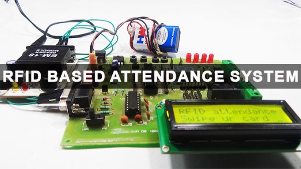
Attendance in colleges is generally paper based which may sometimes cause errors. Taking attendance manually consumes more time. So the proposed attendance system uses RFID technology to take attendance. In this system, each student is issued an RFID tag. Controlling unit is in the institute. Whenever the card is placed near the reader, it will take the attendance. This article explains the same. But, before going to read this post, once get an idea about how to interface LCD with AVR Microcontroller as it is also included in this circuit.
Construction and Output Video
RFID Based Attendance System Circuit Principle:
RFID based attendance system consists of RFID Reader, RFID Tag, LCD display and microcontroller unit. RFID can be interfaced to microcontroller through USART. Data is transferred from RFID cards to reader and from there to microcontroller.
Radio frequency technology is used in many applications. RFID tags are of two types – 1) Passive Tags and 2) Active Tags. Passive tags contain 13 digit number tag inbuilt in it, where as active tag is read/write tag i.e. one can read from the tag and write to the tag. This project uses passive tag. In real time, one can issue active tags to the students, with their roll numbers as their tags. RFID reader contains a copper winding in it. This winding acts as an antenna.
When the tag is placed near the reader, due to the induced mutual inductance energy, data is transferred to reader. Reader then transfers data to the microntroller. Microcontroller checks for the data continuously, if any data is received, microcontroller compares the data in data base. If the tag is authenticated, microcontroller takes the attendance. Also you can check out the rfid based attendance system output video.
RFID Based Attendance System Circuit Diagram:
Circuit Components:
- ATMEGA8 Microcontroller.
- RFID Reader
- RFID Tags.
- LCD display
Circuit Design of RFID Based Attendance System:
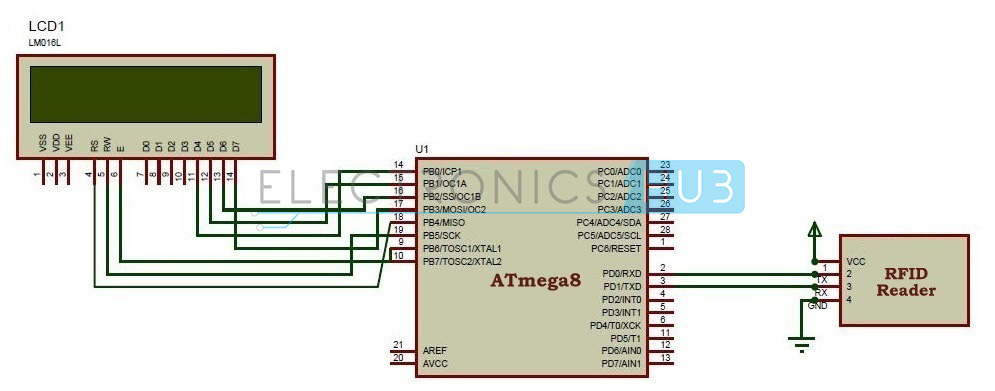
RFID based attendance system has very simple circuit design. The RFID Reader has transmit and receive pins. These pins are connected to the transmit and receive pins of the micro controller i.e. PD0 and PD1 pins of microcontroller.VCC is connected to 5v and GND is connected to ground. If pins are not available to the module, connect it using DB9 connector. PD0 pin is receiver and PD1 pin is transmitter.
Related Post: Biometric Attendance System using AVR Microcontroller.
RFID module communicates with the controller using USART, where USART is a communication protocol. USART is acronym for Universal Synchronous and Asynchronous Receive and Transmit. Serial data can be transmitted from RFID module to microcontroller using UART.
ATMEGA8 microcontroller has USART registers internally. One should declare these registers in order to transmit or receive data serially.
LCD display is connected to Port B of the microcontroller. Interfacing of LCD in 4 bit mode is in to microcontroller which is shown in the circuit diagram. D4 – D7 data pins are connected to the PB0 – PB3 pins of microcontroller. RS pin is connected to PB4, RW pin is connected to PB5 and enable pin is connected to PB6 of microcontroller. To display data on LCD, initially set the LCD in 4bit mode. Then make Rw pin low, RS pin high, enable pin high. Send the data on data pins and make enable pin low.
DOWNLOAD PROJECT CODE
RFID based Attendance System Circuit Simulation Video:
How to Operate RFID Based Attendance System Circuit?
- After making all the above connections, Switch on the circuit.
- On LCD it is displayed “PLEASE SWIPE THE CARD”.
- Place the RFID tag near the reader.
- Reader then reads the data in the tag and transmits to the controller.
- Microcontroller compares the tag with the database. If the tag is matched LCD displays “authenticated” and takes your attendance
- Now place another card which is not present in the database and check for authentication.
- Now LCD displays “Unauthorised” and it will never take the attendance.
- In this way, we can use implement this circuit.
Output Video (RFID Attendance System using AVR)
Circuit 2 RFID based Attendance System using 8051
The above circuit shows RFID based attendance system using AVR. Here is the same project but using 8051 microcontroller. Let us see the circuit and working of this circuit.Circuit working principle is same as the above circuit.
Circuit Diagram
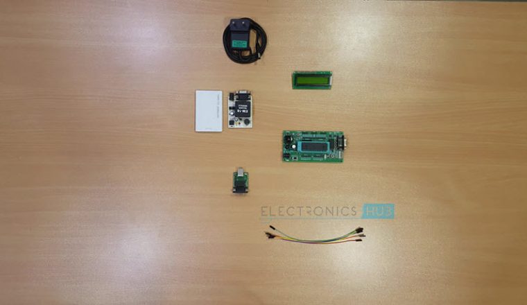
Components Required
- AT89C51 Microcontroller
- AT89C51 Programming Board
- 11.0592 MHz Quartz Crystal
- 2 x 33pF Ceramic Capacitors
- 2 x 10KΩ Resistor
- 10µF Electrolytic Capacitor
- 2 x Push Button
- 16 x 2 LCD Display
- 3 x 1KΩ Resistor
- 10KΩ POT
- EM-18 RFID Reader Module
- RFID Tags or Cards
- Connecting Wires
Circuit Design
The main components of the project are 8051 based microcontroller, 16×2 LCD, and RFID reader module.
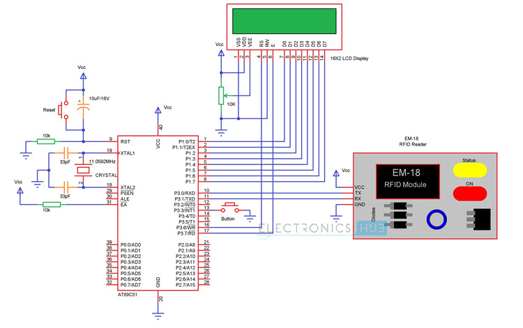
First we’ll see the basic connections with respect to the microcontroller. Here, we’ll need to connect a crystal, a reset circuit and external access.
To use the on-chip oscillator, an 11.0592 MHz quartz crystal is connected to pins 18 (XTAL2) and 19 (XTAL1) of the microcontroller. Two 33pF ceramic capacitors are connected from the crystal to ground.
The reset on the 8051 microcontroller is active high i.e. upon applying a high pulse to RST pin, the microcontroller will reset. A 10KΩ resistor is connected from the RST (Pin 9) of the microcontroller to ground.
A 10µF electrolytic capacitor is connected between the positive supply and RST pin. A push button is connected across the capacitor.
The External Access pin (Pin 31) is connected to positive supply using a 10KΩ resistor. This completes the basic connections with respect to microcontroller.
Now we’ll connect the LCD to microcontroller. To adjust the contrast of the display, a pot is connected to contrast adjust pin i.e. Pin 3 of LCD.
First, connect the three control pins of the LCD i.e. RS, RW and E to P3.6, GND and P3.7. Then connect the 8 data pins of the LCD display to PORT1 pins of the microcontroller.
After connecting the display, now we are going to connect the RFID reader module. Connect the TX pin of RFID Reader to RXD pin i.e. P3.0 of the microcontroller. Similarly, connect the RX pin of RFID Reader to TXD pin i.e. P3.1 of the microcontroller.
Finally, a button is connected to P3.3 (IN) to view the attendance details.
Working
The aim of this project is to design an RFID Technology based Attendance System using 8051 microcontroller, in which the attendance of students or employees is automatically recorded with the swipe of a card. The working of the project is explained here.
When this circuit is powered ON, initially the microcontroller will display the message as Swipe the card on the LCD display. When the RFID reader detects the ID card, it will send the unique card no to the microcontroller via serial terminal.
With the help of suitable programming, we need to compare the received card no. with the numbers that are already stored in the microcontroller or any database.
Once, if any of these numbers are match with the received card no., then the corresponding name stored in that no. is displayed on the LCD display and also the attendance for the name stored in the corresponding number is marked.
By pressing the button, the attendance recording will be closed and the details are displayed on the LCD repeatedly until the microcontroller has been reset.
DOWNLOAD PROJECT CODE
Applications of RFID Based Attendance System
- RFID based attendance system can be used in educational institutions, industries, anywhere.
- RFID is emerging technology and is used in applications where authentication is needed.
Limitations of RFID Based Attendance System
- RFID attendance system is secured, but there is a chance of misusing the cards. One person can give another person’s attendance if he/she had RFID card.
- If the card was swiped for more than once, there is a chance of giving attendance for next days also if code is not written properly.
Source : RFID Based Attendance System – Circuit, Working, Source Code
About The Author
Ibrar Ayyub
I am an experienced technical writer holding a Master's degree in computer science from BZU Multan, Pakistan University. With a background spanning various industries, particularly in home automation and engineering, I have honed my skills in crafting clear and concise content. Proficient in leveraging infographics and diagrams, I strive to simplify complex concepts for readers. My strength lies in thorough research and presenting information in a structured and logical format.
Follow Us:LinkedinTwitter