At home I have a few electrical Rolling Shutters that are controlling via a switch with which you can let them go up or down. When the Rolling Shutter reaches the end of its up or down movement, the motor of the Rolling Shutter stops automatically and you can put the switch that controls it in the neutral position.
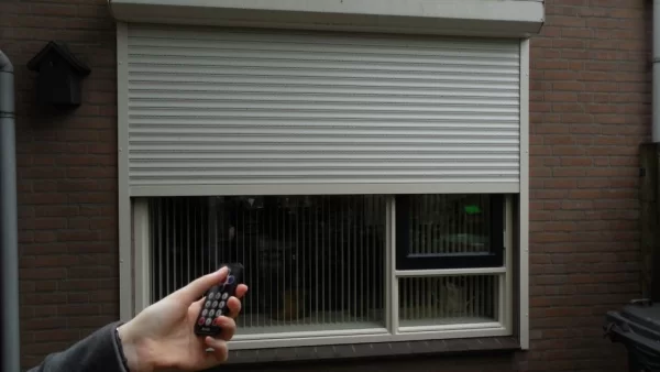
Sometimes I forget to put the switch in the neutral position. This is not a problem since the motor stops by itself but still it would be good not to continuously have the mains power on the Shutter motor. So I thought it would be a nice project to control the Shutter that prevents this and while working on it why not control it via a Remote Control?
This project performs a very simple task. Whenever it receives the correct Remote Control command, it moves the Rolling Shutter up or down or it stops the movement while going up or down if a stop command is given. Since it might be handy to still control the Shutter manually, I also added one push buttong for up and one push button for down
In my situation it takes about 20 seconds to completely open or close the Rolling Shutter so I used 30 seconds as activation time for the control of Rolling Shutter to be sure. I used a Remote Control that is commonly used by Arduino projects which is a Remote Control that uses the NEC protocol. In this case I used it on my favorite controller, the PIC instead of the Arduino.
This project has the following features:
- Moving the Rolling Shutter up using the arrow up key on the Remote Control, command 98
- Moving the Rolling Shutter down using the arrow down key on the Remote Control, command 168
- Stop the movement of the Rolling Shutter using the OK key on the Remote Control, command 2
- Moving the Rolling Shutter up via a push button for up
- Moving the Rolling Shutter down via a push button for down
- Stop the movement of the Rolling Shutter when pressing the up or down push button again during the movement of the Rolling Shutter
As already mentioned I am a big fan of the PIC microcontroller and I like to have full control of what I am creating so I did not use any libraries but created all parts of the software myself. Arduino fans can use of course do the same or use the libraries that are available for e.g. the Remote Control decoding part.
Step 1: Required Components
You need to have the following components for this project:
- PIC microcontroller 12F615
- TSOP4838 IR receiver
- Ceramic capacitors: 2 * 100nF
- Resistors: 3 * 33k, 2 * 180 Ohm, 2 * 1k
- LED: 1 Red, 1 Green
- 2 * push button
- 2 * Relays operating on +5 Volt and capable of switch sufficient mains power.
- 2 * Diode 1N4148
- 2 * BC648 transistor or equivalent
- 1 * 5 Volt Power supply sufficient to power the circuit.
Step 2: Building the Electronics
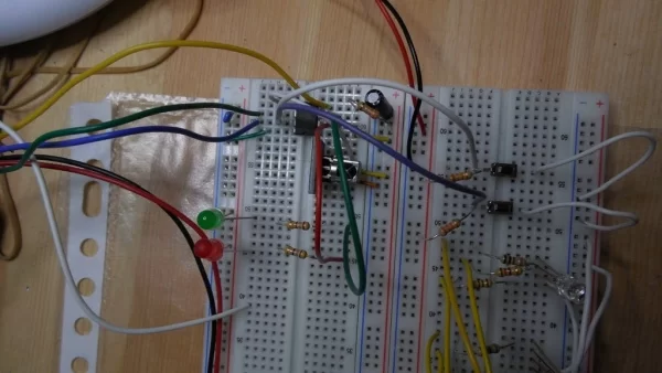
You can build the circuit on a breadboard but be very careful with the Relays that switch the mains power for the motor of the Rolling Shutter. Do not touch the mains power in any way!
Note that I only prototyped this project so I added two schematic diagrams, one of the prototype with only LEDs that show the operation and one that should do the trick if you really want to control the motor of the Rolling Shutter using Relays to switch the mains power.
In the picture you can see the circuit as it was made on a test board.
Attachments
Step 3: The Software
As already mentioned, the software is written for a PIC12F615. It was written in JAL. Since I did not use any specific libraries to total code size is 663 bytes which fits nicely in the 1k program flash memory this specific controller has.
The software performs the following main tasks:
- Decoding the Remote Control messages. For this it uses a capture timer that captures the duration of the bits. The decoding routine works completely interrupt based and uses each changing level of the RC message by constantly changing the interrupt edge level.
- Scanning the up push button and down push button
- Control the up motor and the down motor. Whenever the Rolling Shutter changes direction it first switches off one motor and waits for about 20 ms before switching on the other motor. A motor is activated for a period of 30 seconds. The software always activates only one motor at the same time.
The PIC controller runs on an internal clock with a frequency of 8 MHz. The Intel Hex file is attached for programming the PIC controller. I added the JAL source files too.
Attachments
Step 4: Operating the Remote Controlled Rolling Shutter
When you turn on the circuit no motor will be activated. When you use the Remote Control or one of the push buttons, the corresponding motor will be activated. Remote Control and Push buttons can be used as you please, that is, the last one used takes over. If the screen is moving up by a Remote Control command then pressing one of the push buttons will stop the movement. Pressing the push button again will control the motor in the selected direction.
The video shows the operation using test set-up. The red LED at the top right indicates the down movement, the green LED at the top right indicates the up movement. For this video I reduced the activation time from 30 seconds to 5 seconds. In the video you can see both the control via the Remote Control as well as the control via the push buttons. The video also shows the interruption of the movement when pressing a push button while the movement is still ongoing which can be compared with pressing the stop command on the Remote Control.
Note that in the left bottom left part of this video you also see the prototype of the ‘Pimp your LED Lamp’ project.
Have fun building your own project and looking forward to your reactions.
Source: Remote Controlled Rolling Shutter
About The Author
Muhammad Bilal
I am a highly skilled and motivated individual with a Master's degree in Computer Science. I have extensive experience in technical writing and a deep understanding of SEO practices.