
This topic shows an easy and effective way for decoding IR (Infra-Red) remote controls that use Philips RC-5 communication protocol, but first we’ve to understand how the RC5 protocol works.
This Wikipedia links has good infos about the RC5 protocol.
The RC-5 protocol was developed by Philips in the late 1980s as a semi-proprietary consumer IR (infrared) remote control communication protocol for consumer electronics.
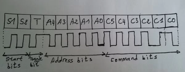
The RC5 has 14 bits per 1 code transmission, the 14 bits can be divided into 4 parts:
The first 2 bits are start bits and they are always logic 1.
The third bit called toggle bit, it can be logic 1 or logic 0.
The next 5 bits are address bits, each device type has its address number for example TV address number is 0, CD player address = 20 …………
And the last 6 bits are command bits, each button has its command number.
For the same device for example TV all the remote control buttons has the same address but each button has its command.
The toggle bit changes whenever a button is pressed.
The RC5 protocol uses Manchester coding, logic 1 and logic 0 are coded as shown in the following drawing where toggle bit is 1, address = 0 and command is 2:
RC5 Protocol state machine:
I used the state machine shown below for decoding the RC5 protocol. The RC5 state machine checks the length of pulses and spaces transmitted from the remote control to go from state to another.
Where:
SP : Short Pulse (About 889µs)
LP : Long Pulse (About 1778µs)
SS: Short Space (About 889µs)
LS : Long Space (About 1778µs)
Basically there are 4 states: Mid1, Mid0, Start1 and Start0.
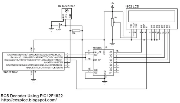
RC5 IR Remote Control Decoder with PIC12F1822 Microcontroller Circuit:
Components List:
- PIC12F1822 Microcontroller
- 1602 LCD
- 74HC595 Shift Register (74HC164, CD4094 ….)
- IR Receiver
- 47µF Capacitor
- 10K Resistor
- 10K Variable Resistor
- +5V Power Supply
- Protoboard
- Jumper Wires
To interface 1602 LCD with PIC12F1822 microcontroller we need 74HC595 shift register as what was done in this post:
Interfacing PIC12F1822 microcontroller with LCD display
The IR receiver is used to receive the IR signals transmitted from the remote control and convert this signals to a digital data (logic 0 and logic 1). The microcontroller reads digital data from the IR receiver, this data is decoded and the results displayed on the 1602 LCD.
Read more: RC5 IR Remote Control Decoder with PIC12F1822 Microcontroller
About The Author
Ibrar Ayyub
I am an experienced technical writer holding a Master's degree in computer science from BZU Multan, Pakistan University. With a background spanning various industries, particularly in home automation and engineering, I have honed my skills in crafting clear and concise content. Proficient in leveraging infographics and diagrams, I strive to simplify complex concepts for readers. My strength lies in thorough research and presenting information in a structured and logical format.
Follow Us:LinkedinTwitter