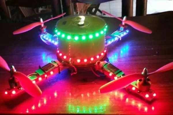
Although there are MANY good circuits available on the internet for similar projects, I had a dedicated problem to solve. Most of the circuits available switches their outputs on at mid stick position (50%). My drones all use six channels (Throttle, Aileron, Rudder, Elevator, GPS Mode, Flight Mode), thus not leaving any spare channel to control my LED lights. My idea was thus to make use of the throttle channel to also control my lights.

With my drones, using either ArduPilot or Naza controllers, they all will start to lift of at mid throttle (50%). Thus I decided to build this circuit to switch on the LEDs at around 10% throttle.
Size of the circuit was critical, as well as using “mostly” through-hole components.
I have opted to use the Microchip PIC 12F675, and a darlington driver transistor
Step 1: Circuit Diagram
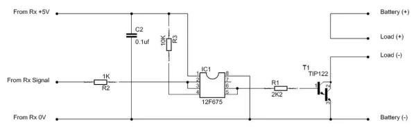
No special or complex circuitry… The circuit itself is powered from the receiver, and the signal from the receiver is fed into the PIC via a protection resistor (1K). The PIC uses internal pull-up resistors on this input, thus eliminating one external resistor.
The output of the PIC drives a TIP122 darlington transistor to switch the load on and off. The transistor is capable of switching up to 2A at 14.4V without the need for any heat sink.
The load or LEDs are connected to a seperate battery (or the electric motor battery), and not from the receiver.
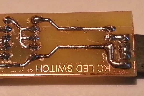
Step 2: PC Board Design
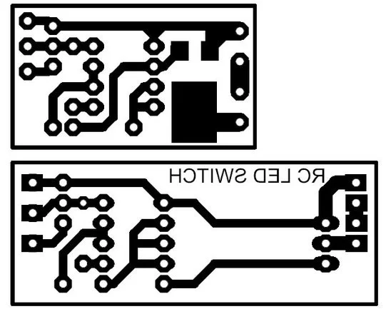
I have made two versions, one using a standard TIP122, and the other a MJD122G, which is a DPACK version of the TIP122. Although this is a surface mount component, it is still easy to solder onto the PC board.
The PC boards were designed on the free version of Eagle. With the 100mm x 80mm size limitation of the free Eagle version, I was still able to fit 12 SMD boards, or 8 TIP122 boards per design.
Attachments
Step 3: Size of Completed Design
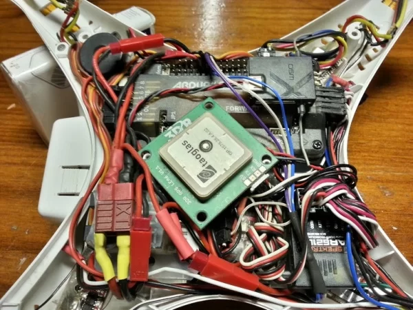
As can be seen in the picture, space was really a BIG ISSUE on my self-build Phantom. With the SMD version, fitting was really easy. The circuit is only 30mm x 18mm after it was covered in heat shrink, easy to fit almost anywhere.
The bigger circuit works well in airplanes where space is not as limited. I have also added headers for easy connection to lights and batteries, but it does take up more space.
Step 4: Programming the 12F675
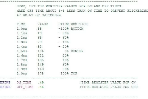
The On and Off positions can easily be changed in the ASM file. I have added some typical values for different stick positions if you want to change the values.
I suggest that the On and Off values should be about 4 counts apart to prevent flickering right at the turn-on stick position.
I have also included the HEX file for direct programming to the 12F675.
With the default values, the LEDs turn on at around 10% throttle, and will turn of at about 8%.
Attachments
Step 5: Building the Circuit
Building the circuit is simple, and can be done in a few minutes. I recommend that the 12F675 be soldered directly onto the PC board without the IC socket.
For the wiring, I use faulty servo leads for all wiring (I have a constant supply from our club members)
NOTE:
Please use silicon wire for all wiring. The insulation of non-silicon wire tend to creep away at the soldering points. As the space between the soldering points are close together, this could lead to a short circuit, and potential crash.
Step 6: Testing
There is a self-test feature, where the LEDs will turn on for 1 second when the receiver is switched on. This is followed by 1 second with LEDs off.
In case of loss of signal, the LEDs will be switched on.
If, after programming, the self test does not work, check if the wiring is correct. If correct, make sure that the 12F675 contains valid calibration data. The software loads the calibration data at start-up, and if this data has been overwritten at a previous stage, this will result in the 12F675 continuously rebooting.
I have used both versions for some time now on the following:
– 2 x self-build quadcopters (including Phantom body)
– DJI 450 Flamewheel
– DJI 550 Flamewheel
– Sail yacht
– RC Bait boat
– Several night flight airplanes.
Step 7: Connecting the Circuit
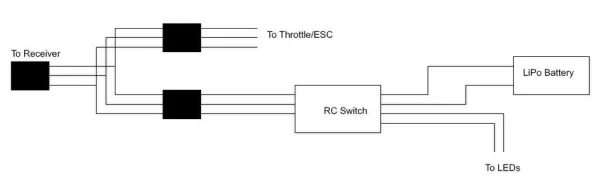
I connect the circuit to the receiver throttle channel via a Y-lead.
Although I designed the circuit to be used on the throttle channel, it can be connected to any spare receiver channel as well. You will just have to set the endpoints or travel adjustments on your transmitter.
Source: R/C Controlled Switch for Drones
About The Author
Muhammad Bilal
I am a highly skilled and motivated individual with a Master's degree in Computer Science. I have extensive experience in technical writing and a deep understanding of SEO practices.