
Contents
hide
This application note addresses the various
requirements for protecting the Universal
Serial Bus (USB) from overcurrent and over
voltage environmental threats.The solutions
presented cover both USB 1.1 and the
higher speed USB 2.0 circuitry. Specific
emphasis is placed on USB 2.0 with infor-
mation directed at hot connection over
current conditions and electrostatic
discharge (ESD) induced in the USB system.
The USB Standard
The USB specification provides a uniform
protocol for the addition and configuration
of computer peripherals. USB is designed
around one uniform port size and a match-
ing connector. It uses the concept of a
single host and multiple hubs designed to
provide uniform and simple methods for
adding and connecting various peripherals.
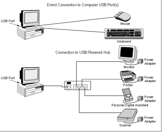
The goal of USB is to reduce the number
of cable connections and configurations.A
single USB port has the capability of driving
up to 127 USB peripherals such as mice,
modems and keyboards (see Figure 1).
Additionally, a single hub permits the
connection of several USB devices by
providing power through the communica-
tion cable itself, eliminating the need for
individually powered peripherals. It also
allows mixed high-speed communications
between USB and other protocols
such as Ethernet, DSL, ISDN or
satellite communications
USB is an external bus standard that
supports data transfer rates of up to 12Mbps
for USB 1.1 and 480Mbps for the new USB
2.0 standard. USB also supports Plug-and-
Play installation and hot plug operation.
USB 2.0 addresses the evolution to higher
data transmission rates between computers
and peripherals or networked LAN or
WAN systems. Recent data protocols now
reach millions to billions of characters
per second.
The integrated circuits required to support
this high-speed technology become increas-
ingly complex, shrinking feature size and
making them more susceptible to over
current and over voltage occurrences.
Over current Protection
for USB Power Rails
The USB port consists of four lines – two
data lines (D+ and D-),Vbus and GND.
which connect the USB Hub to the USB
peripheral. Overcurrent protection is not
normally required on the two data lines
or GND.
USB ports can be configured two different
ways:As Self-powered ports or Bus-
powered ports.A Self-powered USB Hub
must have the capability to source up to
500mA on Vbus on all of its ports.A Bus-
powered Hub does not draw power from
the USB stream, but may utilize up to
100ma from upstream devices or hubs to
allow for functionality of the hub when it is
powered down.
Bus-powered Hubs can draw up to 500mA
from an upstream self-powered connection.
Typically 100mA is available for functions
and processors internal to the hub. External
ports in a Bus-powered Hub can supply up
to 100mA per port, with a maximum of 4
ports per hub.
USB Bus Transceiver ICs or Po
For more detail: Protecting the Universal Serial Bus fromOver Voltage and Overcurrent Threats
About The Author
Ibrar Ayyub
I am an experienced technical writer holding a Master's degree in computer science from BZU Multan, Pakistan University. With a background spanning various industries, particularly in home automation and engineering, I have honed my skills in crafting clear and concise content. Proficient in leveraging infographics and diagrams, I strive to simplify complex concepts for readers. My strength lies in thorough research and presenting information in a structured and logical format.
Follow Us:LinkedinTwitter