
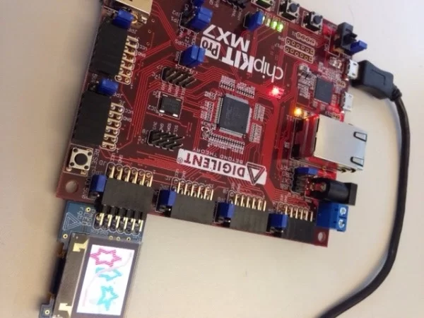
LED screens are everywhere. Chances are you’re using one to read this right now. With the release of Digilent’s PmodOLEDrgb, now you can program one yourself!
Step 1: Materials
For this project you’ll need:
- chipKIT Pro MX7
- PmodOLEDrgb
- Micro USB cable
- MPIDE installed
- Python installed (for converting bitmaps)
- PmodOLEDRGB libraries
Step 2: Install the PmodOLEDrgb Library
Extract pmodoledrgb_lib_mpide.zip
Copy the “OLEDrgb” folder into your Documents>mpide>libraries folder. If this folder doesn’t exist, open up MPIDE to automatically generate the folders.
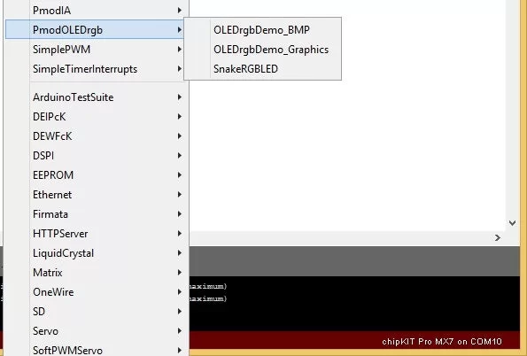
Once it is copied, restart MPIDE and click the Open button. You should see OLEDrgb in the drop down menu.
This PmodOLEDrgb library contains several useful functions that make interfacing with the PmodOLEDrgb much simpler. It takes care of all of the timing and individual SPI transmissions that happen between your board and the Pmod.
Step 3: Plug in the PmodOLEDrgb
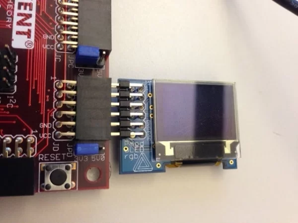
The library requires that the PmodOLEDrgb be connected to DSPI0 on your PIC32. On the chipKIT Pro MX7, this is found on Pmod port JD. Plug your PmodOLEDrgb into port JD.
Step 4: Create a New Sketch
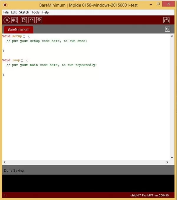
Click Open, go down to 1.Basics, and open the BareMinimum project.
Go to File and click Save As. Name and save it.
Step 5: Include and Instantiate
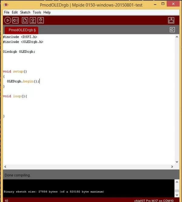
Next up, we need to include the necessary libraries. Add the following lines to the beginning of your program.
#include <DSPI.h>
#include <OLEDrgb.h>
Oledrgb OLEDrgb;
This will include the SPI and the OLEDrgb libraries, and will instantiate an Oledrgb object named OLEDrgb.
Inside the setup() function, add the following line:
OLEDrgb.begin();
This function goes through the powering on sequence and configuration that the PmodOLEDrgb must go through to operate correctly.
Step 6: Using the Library Graphics Functions
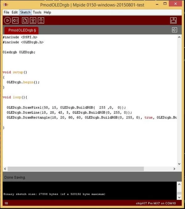
You can find several functions within the OLEDrgb.c file included in the library. These functions include DrawPixel, DrawLine, DrawRectangle, and DrawBitmap. There is also a helper function called BuildRGB(red,green,blue) that formats the RGB color into 2 bytes that can be read by the PmodOLEDrgb.
Calling OLEDrgb.DrawPixel(50, 15, OLEDrgb.BuildRGB( 255 ,0, 0)) will draw a pixel at coordinate (50,15) colored red.
Calling OLEDrgb.DrawLine(10, 20, 45, 5, OLEDrgb.BuildRGB(0, 255, 0)) will draw a line from (10,20) to (45, 5) colored green.
Calling OLEDrgb.DrawRectangle(10, 20, 80, 60, OLEDrgb.BuildRGB(0, 255, 0), true, OLEDrgb.BuildRGB(0,0,255)) will draw a green rectangle from (10,20) to (80,60). True signifies that it will be filled in, and the last parameter sets that the fill will be blue.
Plug your chipKIT Pro MX7 into your computer via UART and select it in MPIDE by clicking Tools>Board>chipKIT>chipKIT Pro MX7. Select the serial port that your board is plugged into by clicking Tools>Serial Port>COM_. Once you are all set up, click the Upload button to upload it to your board.
Step 7: Displaying a Bitmap Part 1
Displaying a bitmap using the OLEDrgb library requires us to first turn it into a byte array. I created a python script that does this, but first we need a bitmap.
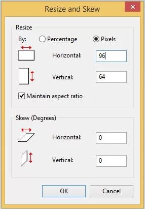
Open paint and click on Resize. Resize the image to 96 pixels horizontal by 64 pixels vertical.
Let your imagination run wild. When you are finished, save the image as a 24-bit bitmap.
Copy the bitmaptoarray.py script into the same folder as your masterpiece and run it. When prompted, enter the name of your bitmap file and press enter. If it worked you should see “Byte array created as masterpiecearray.c!” Within your folder, you should see a new .c file that contains your array.
Attachments
Step 8: Displaying a Bitmap Part 2
Copy and paste the array into your MPIDE sketch above the setup() function.
Now, inside of you setup() function, but after OLEDrgb.begin() copy the following line into your code
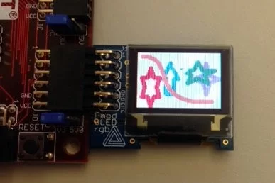
OLEDrgb.DrawBitmap(0,0,95,63, (uint8_t*)masterpiece);
This will draw your masterpiece array from (0,0) to (95, 63) when your program is run.
Click Upload to program your board. You should eventually see your masterpiece on the PmodOLEDrgb!
Step 9: Snake!
For a more advanced example, check out the SnakeRGBLED sketch included in the OLEDrgb library. It requires a PmodBTN, or at least a 4 button setup on Pmod port JF.
This example does a couple of cool things with the PmodOLEDrgb. The title screen features a snake that sticks its tongue out periodically. This is done by loading several different frames using the DrawBitmap function. The game itself uses a scaling algorithm to scale a 48 by 32 grid onto the 96 by 64 OLED. Better yet, you get to play Snake!
Source: Programming the PmodOLEDrgb on the ChipKIT Pro MX7
About The Author
Muhammad Bilal
I am a highly skilled and motivated individual with a Master's degree in Computer Science. I have extensive experience in technical writing and a deep understanding of SEO practices.