
Team Members
- Amanda Care (Senior in Mechanical Engineering, Northwestern University)
- Eric Nickel (Graduate Student in Biomedical Engineering, Northwestern University, BS in Biomedical Engineering from the Milwaukee School of Engineering)
- James Yeung (Junior in Electrical Engineering, Northwestern University)
Overview
The “Programmable Stiffness Joint” is a device which is able to internally modify the rotational stiffness of a simple pivot joint. It is intended to serve as a proof-of-concept for future work in developing a model for determining the respective damping and stiffness components of the human ankle joint over the able-bodied gait cycle. This information in turn will permit prosthetists and rehabilitation engineers to design and fit prostheses better designed for the user’s gait kinetics, which in turn should produce more natural gait kinematics.
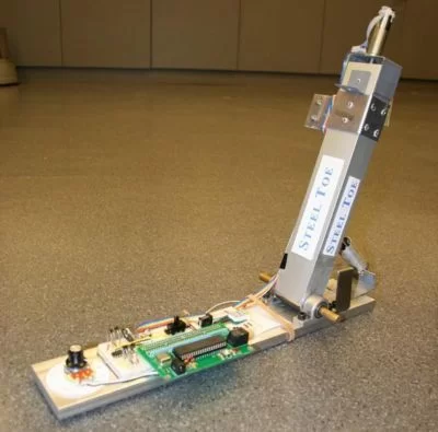
The goal of our project is: To develop a working model of a device which is able to control the stiffness of a joint in such a manner as to mimic the motion of a human ankle joint. The user is able to select a stiffness level and the device will adjust itself to provide the specified level of rotational stiffness. The set-point of the joint will remain constant for all stiffnesses.
This is how it works: A linear coil extension spring has a constant stiffness within its elastic extension limit. As the location of the insertions of the spring on the base and rotating member change position, the amount of spring extension experienced for a given angular change of the rotating member will vary, as will the torque produced by the spring tension. These variations are taken advantage of to produce widely different stiffnesses from a single linear extension coil spring.
We will discuss:
- Stiffness theory and the conceptual framework which guided the design of the device
- Mechanical design and function of the device
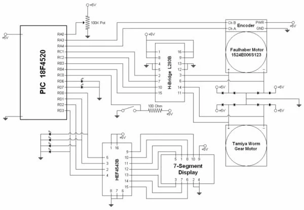
- Electrical design and function of the device
- PIC control and the software developed to control the device
- Results of final testing
- Future work and lessons learned
Stiffness Theory
The rotational stiffness of a joint is defined as the torque required to cause a given angular rotation.
Fundamental Equation
Based upon the diagram at right, the following variables are defined for these equations:
- L1 = The distance from the pivot point to the “heel” insertion point of the linear spring on the base plate
- L2 = The distance from the pivot point to the “shank” insertion point of the linear spring on the rotating element
- L3 = The distance between the two insertion points
- h = The height of the insertion point on the rotating member for a given angle and L2
- a = The horizontal component of the position of the insertion point location on the rotating member for a given angle and L2
- theta = The angle of the rotating member with respect to the vertical (perpendicular to the base plate)
- beta = The angle of the spring tension with respect to the rotating member
Below is the bottom line for rotational stiffness. For more detailed information, see the separate Rotational Stiffness page.
There are three major aspects to consider for rotational stiffness:
First, a linear spring requires a constant incremental force to achieve a given incremental change in the spring length. This is described by Hook’s Law (shown below) where F is the force applied to the spring, x is the change in length of the spring (in this case, it will only be extension), and k is the stiffness of the linear spring.
F = k * x
Due to this relationship, the amount of extension of the spring will determine the tension force applied to the sliding insertion point on the rotating member. Therefore as the amount of spring extension increases, the amount of rotational stiffness increases.
Secondly, a torque (T) is the result of a force (F) applied at a distance (d) from the axis of rotation. As the distance from the axis increases, the torque produced by a given tension force increases, therefore the rotational stiffness increases.
T = F * d
Lastly, the angle (beta) between the tension force and the rotating member matters. Only the component of the force which is tangential to the rotation is generating torque. The rest of the force becomes a compressive force in the rotating member, and does not contribute. As the angle between the spring and the vertical member decreases, the rotational stiffness decreases.
F(tangential) = F(tension) * sin(beta)
This all condenses into the following torque formula in terms of the variables from the conceptual diagram:
T = k * ( (L2*cos(theta))^2 + (L1+L2*sin(theta))^2 )^1/2 * sin(beta) * L2
beta = pi / 2 − theta − arctan(h / a)
MATLAB Simulation
Simulations of the above theory in MATLAB produced the following results.
Over the range of motion of this device (-20 degrees to +30 degrees) the spring stretch is pretty close to linear. This suggests that there will be limited change of joint rotational stiffness due to non-linear spring stretch.
As the L2/L1 ratio increases, there seems to be a plateau for L2/L1 > 2. This suggests that the torque gain due to spring tension in this region would be minimal.
The peak torque produced by the spring seems to be at a ratio of L2/L1 = 1. Above this point, the angle beta is too small, and not enough of the spring tension force is tangential to the rotation, so the torque actually decreases. Below this ratio, the amount of spring stretch is decreasing, resulting in reduced torque. The ideal region to be working within is the region:
0 < L2 / L1 < 1
| Stiffness Level | Force Needed to Get to 90 Degrees |
|---|---|
| 0 | 2.943 N |
| 1 | 3.434 N |
| 2 | 4.415 N |
| 3 | 5.886 N |
| 4 | 7.358 N |
| 5 | 9.810 N |
| 6 | 11.282 N |
| 7 | 12.263 N |
| 8 | 13.734 N |
| 9 | 14.715 N |
For more detail: Programmable Stiffness Joint
About The Author
Ibrar Ayyub
I am an experienced technical writer holding a Master's degree in computer science from BZU Multan, Pakistan University. With a background spanning various industries, particularly in home automation and engineering, I have honed my skills in crafting clear and concise content. Proficient in leveraging infographics and diagrams, I strive to simplify complex concepts for readers. My strength lies in thorough research and presenting information in a structured and logical format.
Follow Us:LinkedinTwitter