Description
Since I published the original RGB LED driver (photo right) I’ve had many enquiries from people asking how they could make the original board work with more LEDs. I’d already made a couple of custom boards up for myself, so I finally decided it was time to put together one for the website.
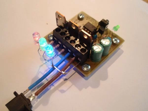
The RGB LED driver described on this page uses logic level ‘N’ channel MOSFETs which allow it to control LED arrays or lamps at up to 5 amps per channel without heatsinks.
The driver uses exactly the same firmware as the small RGB LED driver so you can use the same code and sequences with this board to control big arrays of LEDs.
Piranha LED colour bar
Here’s a one off light bar I built using 20 Piranha RGB LEDs and the (prototype) MOSFET driver board. Assembled into a 25mm x 50mm x 1000mm aluminium ‘U’ section. This was fitted under a wall shelf to illuminate the floor. It’s very bright and gives a nice even illumination without any additional diffuser.
Circuit Description
This circuit is essentially the same as the smaller RGB driver using the 5mm LEDs elsewhere on this website except that this version uses high power MOSFETs capable of sinking 5 amps on each channel without heatsinks (at 5amps the MOSFETs will run hot)
The input power to the board must be regulated DC and be capable of suppling the power requirements of the output load.
The circuit will operate from a supply voltage in the range 9 to 24 volts. This voltage range is dictated by the input requirements of the 78L05 voltage regulator and capacitors C3/4.
Switch S2 is not used with the firmware on this website and you do not need to fit it. I’ve incorporated it the PCB design because I’ve written some customized versions of the code that did require two switches.
How much power can it handle?
During testing I connected the controller to some 50W / 12Volt halogen downlight bulbs, one on each channel then ran them at 100% PWM duty cycle.
| Ambient temperature during test | 22oC |
| MOSFET temperature after 5mins (measured on metal tab) | 52oC |
| Current (sink per channel) | 4.4A |
| Voltage drop across MOSFET Source-Drain terminal (measured) | 20mV |
Based on these measurements and the specification of the MOSFETs and PCB connectors, the controller should comfortably handle 5 amps per channel. While the individual MOSFETs could handle more current, the PCB screw terminal connectors are rated at 16 amps and since there is only a single Ground connection to the board, total load for the three RGB channels should not exceed this.
PCB
PCB only option is available to buy
from the on-line shop page
Component List

Buy the complete kit for this project from the Picprojects on-line shop page
You can buy all the parts needed to build this project from most component suppliers world wide. In the UK you can get everything from Rapid Online and I’ve included a parts list with their part numbers below.
For more detail: Power MOSFET RGB LED PWM Driver for PIC12F683
About The Author
Ibrar Ayyub
I am an experienced technical writer holding a Master's degree in computer science from BZU Multan, Pakistan University. With a background spanning various industries, particularly in home automation and engineering, I have honed my skills in crafting clear and concise content. Proficient in leveraging infographics and diagrams, I strive to simplify complex concepts for readers. My strength lies in thorough research and presenting information in a structured and logical format.
Follow Us:LinkedinTwitter