PLC (Power Line Communication) is the technology that allows data transmission over the existing Power Line network. Power Line can be the home power network or the national electricity transmission grid. The data that can be transferred is as diverse as its speed. With speeds of nearly 200Mbps, video transmission, voice, data and any other services can be transmitted successfully.
On this article i’m going to describe in detail my B.Sc Thesis in department of Electronic Computer Systems Engineer at Technological Education Institute of Piraeus, October of 2012 in Greece.
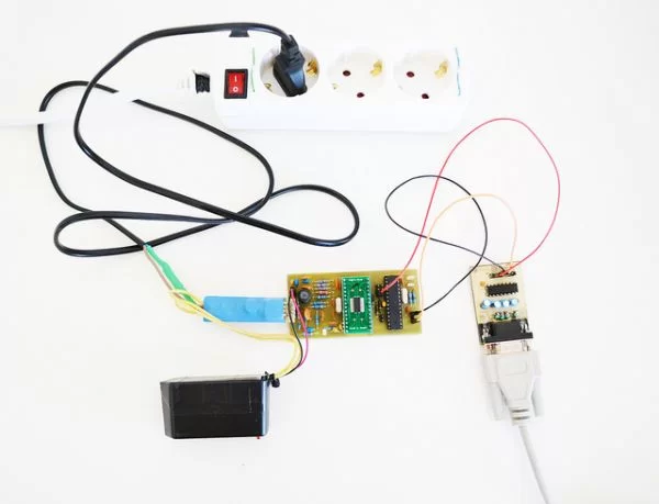
The project includes the design of two modules (transmitter – receiver) implementing a serial communication over the Mains connecting a remote large display to a weighing machine.
The main idea:
The main idea of the communication process is simple described in the following diagram.
From right to left, data to be transmitted are first modulated (digital bits are converted to analog frequency/sine wave e.g. bit 1 is converted to a sine wave of 10Khz bit 0 is converted to a sine wave of 20Khz). In order to “clear” the Mains frequency and make the wire available for the transmitter the 50/60Hz signal is filtered. This filter clears any signal of 50Hz to 60Hz. The transmitted data then are free to travel over the Mains. When they find their destination another 50 to 60Hz filter is involved. After the filter pass the remaining signal is the modulated transmitted data. This signal is now demodulated and converted to digital bits.
Convert data in a transferable form (Modulation):
There are different ways to modulate digital bits to a transferable frequency. I’ll describe the most commonly used types.
In FSK modulation, digital information is transmitted through discrete frequency changes of a carrier signal. For example bit 0 is modulated to a sine wave of 10Khz and bit 1 to 20Khz.
FDM is an encoding method of digital data on multiple carrier frequencies. This method allows simultaneous data transfer on the available frequency range. Firstly the information to be transmitted is separated to pieces. Each piece is modulated to a specific frequency in the available frequency range. Then all the modulated signals are multiplexed to a single signal ready for transmission.
UPB is a communication protocol specially designed for home automation devices. It uses power line wiring for signaling and control. The implementation can simple be done by charging and discharge a capacitor, forming spikes on the current AC signal.
The pulses can be placed on 4 different but specific positions on the current AC wave. It’s like a 4 bit digital number.
The receiver can simple find the position of each pulse by first recognizing the zero crossing and then start counting since the pulse sense.
For more detail: Power Line Communication
About The Author
Ibrar Ayyub
I am an experienced technical writer holding a Master's degree in computer science from BZU Multan, Pakistan University. With a background spanning various industries, particularly in home automation and engineering, I have honed my skills in crafting clear and concise content. Proficient in leveraging infographics and diagrams, I strive to simplify complex concepts for readers. My strength lies in thorough research and presenting information in a structured and logical format.
Follow Us:LinkedinTwitter