pickit 3 Description
Microchip’s PICkit3 In-Circuit Debugger/Programmer uses in-circuit debugging logic incorporated into each chip with Flash memory to provide a low-cost hardware debugger and programmer.
The MPLAB PICkit3 allows debugging and programming of PIC® and dsPIC® Flash microcontrollers at a most affordable price point using the powerful graphical user interface of the MPLAB Integrated Development Environment (IDE). The MPLAB PICkit3 is connected to the design engineer’s PC using a full speed USB interface and can be connected to the target via an Microchip debug (RJ-11) connector (compatible with MPLAB ICD 2, MPLAB ICD 3 and MPLAB REAL ICE). The connector uses two device I/O pins and the reset line to implement in-circuit debugging and In-Circuit Serial Programming™.
pickit 3 Features
- Full-speed USB support using Windows standard drivers
- Real-time execution
- Processors run at maximum speeds
- MPLAB IDE compatible (free copy included)
- Built-in over-voltage/short circuit monitor
- Firmware upgradeable from PC/web download
- Totally enclosed
- Supports low voltage to 5 volts (1.8v to 5.0v range)
- Diagnostic LEDs (power, active, status)
- Read/write program and data memory of microcontroller
- Erase of all memory types (EEPROM, ID, configuration and program) with verification
- Freeze-peripherals at breakpoint
- Program up to 512K byte flash with the Programmer-to-Go
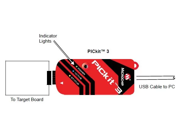
pickit 3 Basic Debugger System
The debugger system can be configured to use standard ICSP communication for both programming and debugging functions.
CAUTION: Do not change hardware connections while the PICkit3 or target is powered.
pickit 3 pinouts connection diagram
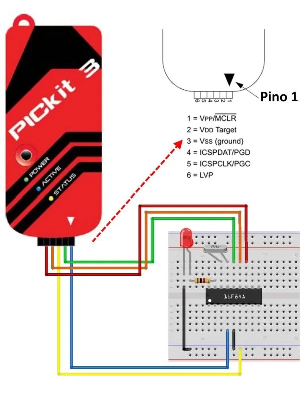
Connecting the PICkit3 to the target board through standard ICSP interface using 6-pin connector. The programmer connector pinout is shown in the figure below:
Be careful on the pin order while connecting.
Incorrect connection may damage the PICkit3 debugger/programmer or the target board.
PICkit3 Status LEDs
The Status LEDs indicate the status of the PICkit3.
- Power (green) – Power is supplied to the PICkit3 via the USB port.
- Active (blue) – The PICkit3 has connection to the PC USB port and the communication link is active.
- Status:
Busy (yellow) – The PICkit3 is busy with a function in progress, such as programming.
Error (red) – The PICkit3 has encountered an error.
Downloads
Development resources:software, datasheets, etc.
Wiki: www.waveshare.com/wiki/PICkit3
About The Author
Ibrar Ayyub
I am an experienced technical writer holding a Master's degree in computer science from BZU Multan, Pakistan University. With a background spanning various industries, particularly in home automation and engineering, I have honed my skills in crafting clear and concise content. Proficient in leveraging infographics and diagrams, I strive to simplify complex concepts for readers. My strength lies in thorough research and presenting information in a structured and logical format.
Follow Us:LinkedinTwitter