
This PIC16F877A microcontroller tutorial answers the question,
” How to use timer0 of PIC16F877A and how to handle its interrupts? ”
Using PIC16 simulator (Proteus) you can verify this PIC timer0 code and change it according to your needs. This code is written in C language using MPLAB with HI-TECH C compiler. You can download this code from the ‘Downloads‘ section at the bottom of this page.
It is assumed that you know how to blink an LED with PIC16F877A microcontroller. If you don’t then please read this page first, before proceeding with this article.
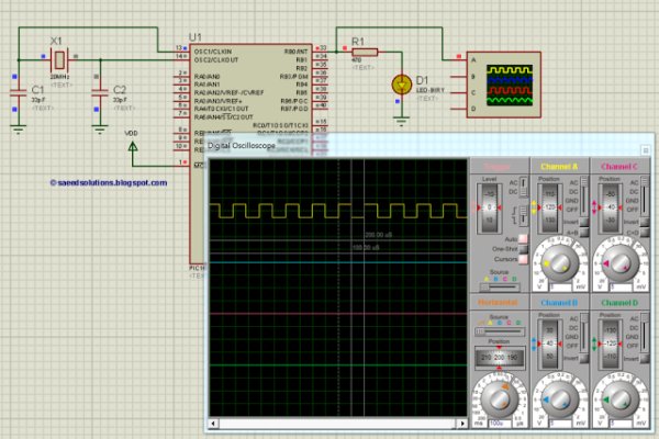
The following diagram (made in Proteus) shows the PIC microcontroller circuit diagram.
In this circuit, PIC16F877A is running on external crystal of 20MHz value. RB0 pin is toggled every time timer0 expires and executes it’s ISR[1] code. In the above figure, it is clear that after approximately every 100usec, RB0 pin is toggled i-e timer0 expires. You can easily change this value in the code.
Code
The main function code is shown below.
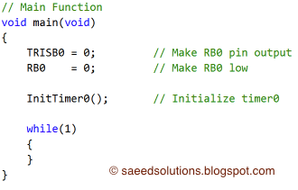 |
| Main function for timer0 of PIC16F877A |
In the main function, firstly TRISB0 is made zero to make RB0 pin an output pin, also RB0 pin is made zero. After that, InitTimer0() function is called which initializes timer0. Rest of the work is done in timer0 interrupt service routine. Every time timer0 expires RB0 pin is toggled.
The code used to initialize timer0 is shown below.
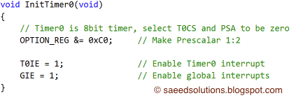 |
| InitTimer0 function code for PIC16F877A |
 Timer0 interrupt service routine code is shown below.
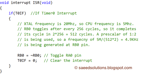 |
| Timer0 interrupt service routine |
This is just an example code for timer0 of PIC16F877A microcontroller. You can modify it to fulfill your circuit requirements.
For more detail: PIC16F877A timer0 code + Proteus simulation
About The Author
Ibrar Ayyub
I am an experienced technical writer holding a Master's degree in computer science from BZU Multan, Pakistan University. With a background spanning various industries, particularly in home automation and engineering, I have honed my skills in crafting clear and concise content. Proficient in leveraging infographics and diagrams, I strive to simplify complex concepts for readers. My strength lies in thorough research and presenting information in a structured and logical format.
Follow Us:LinkedinTwitter