This PIC16F877 microcontroller tutorial answers the question,
“How to interface LCD[1] in 4bit mode with PIC16F877″ ?
Also, using PIC16 simulator (Proteus) you can verify this LCD code and change it according to your needs. This code is written in C language using MPLAB with HI-TECH C compiler. You can download this code from the ‘Downloads‘ section at the bottom of this page.
It is assumed that you know how to blink an LED with PIC16F877 microcontroller. If you don’t then please read this page first, before proceeding with this article.
The following diagram (made in Proteus) shows the PIC microcontroller circuit diagram.
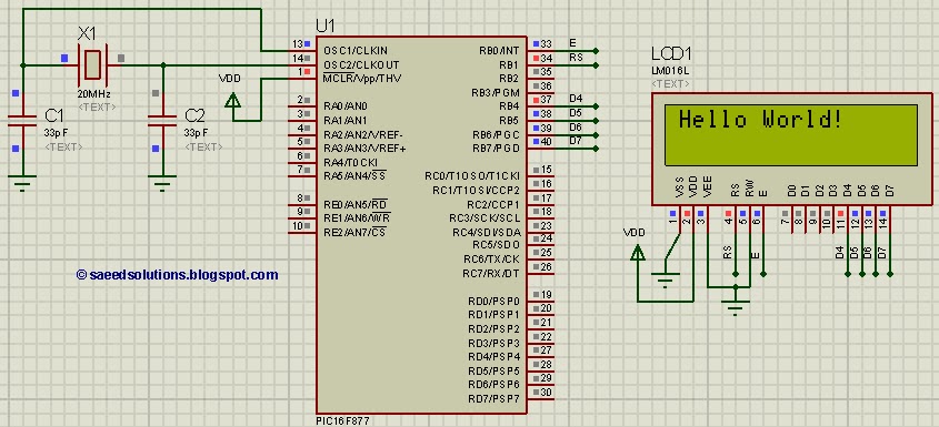
In the above figure, RB0 pin is being used as Enable pin for LCD. RB1 pin is used as RS pin and PORTB (RB4 to RB7) pins are used as Data bus for the LCD. When code starts running then ‘Hello World!‘ is displayed on the LCD.
Code
The code for the main function is shown below.
Downloads
LCD interfacing code using PIC16F877 was compiled in MPLAB v8.85 with HI-TECH C v9.83 compiler and simulation was made in Proteus v7.10. To download code and Proteus simulation click here.
For more detail: PIC16F877 LCD interfacing code (In 4bit mode) and Proteus simulation
About The Author
Ibrar Ayyub
I am an experienced technical writer holding a Master's degree in computer science from BZU Multan, Pakistan University. With a background spanning various industries, particularly in home automation and engineering, I have honed my skills in crafting clear and concise content. Proficient in leveraging infographics and diagrams, I strive to simplify complex concepts for readers. My strength lies in thorough research and presenting information in a structured and logical format.
Follow Us:LinkedinTwitter