This PIC16F877 microcontroller tutorial answers the question,
” How to implement a controllable digital clock using PIC16F877 ? ”
Using PIC16 simulator (Proteus) you can verify this digital clock code and change it according to your needs. Using three push buttons (As shown in figure below) you can adjust time as you desire. This code is written in C language using MPLAB with HI-TECH C compiler. You can download this code from the ‘Downloads‘ section at the bottom of this page.
In this article, it is assumed that you know,
- How to make a simple digital clock using PIC16F877. If you don’t then please read this page.
- How to interface LCD with PIC16F877 microcontroller. If you don’t then please read this page.
- How to configure timer0 of PIC16F877 microcontroller. If you don’t then please read this page.
The following diagram (made in Proteus) shows the PIC microcontroller circuit diagram.
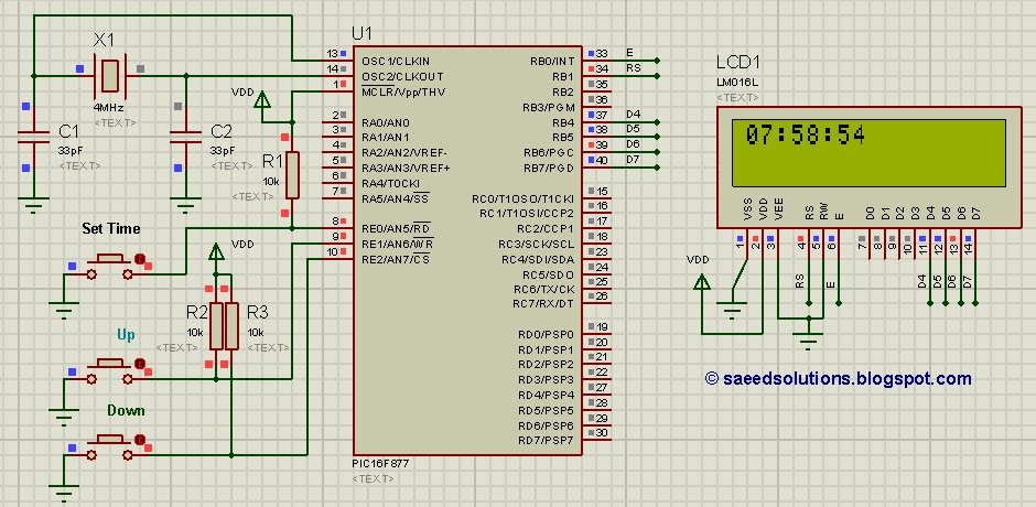
The above figure was taken after setting time to 07:58:54, timer0 is used as the base for digital clock generation. Timer0 is used here to generate 1msec interrupts. After every 1msec a global variable named msCounter increments. When msCounter reaches a value of 1000 then another global variable named secCounter increments and this process repeats itself. Similarly, when secCounter reaches 60, then minCounter increments. And when minCounter reaches 60 then hrCounter increments. This process continues until hrCounter reaches 24 then all of these variables reset their values. LCD is updated with the new values of hrCounter, minCounter and secCounter after every second.
You can set time using three push buttons attached on RE0, RE1 and RE2 pins (As shown in the above figure). By pressing ‘Set Time‘ button one time, code enters in configuration state. Hours value starts to blink and you can modify it using Up and Down buttons. Pressing Up button increments the value and pressing Down button decrements the value. When you are done setting Hours value, press ‘Set Time‘ button again, then Minutes value will start to blink and you can adjust this value using Up and Down buttons. Similarly, after setting Minutes value, you can press ‘Set Time‘ button again, then Seconds value will start to blink and you can adjust this value using Up and Down buttons. When you are done adjusting the time, then press ‘Set Time‘ button for the last time and this clock will start to work normally.
A crystal of 4MHz value is used in this circuit, which makes this PIC16F877 run at a speed of 1MIPS (Million of instructions per second).
Code
The main function code is shown below.
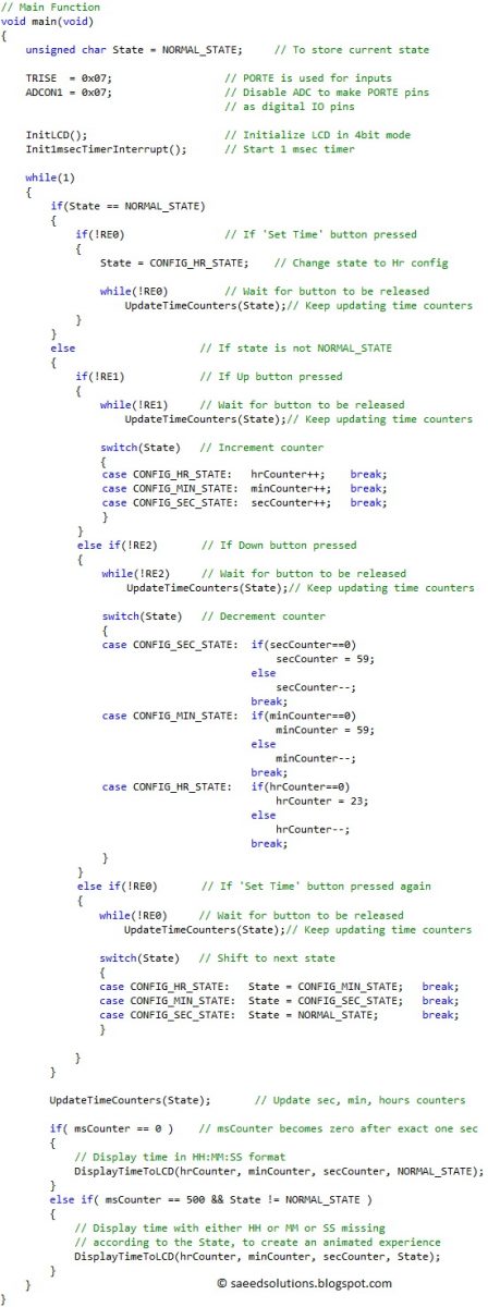
In the main function, firstly PORTE pins are made input and ADC is turned off on these pins. Then LCD is initialized using InitLCD() function. Then Timer0 is initialized to generate 1msec interrupts.
After that, in the while(1) loop, there is a state machine running. A variable named State is used to keep track of the current state of the clock. When this code starts, then State has a value of NORMAL_STATE. In the normal state, clock value is incremented after every second and whenever msCounter reaches a value of zero[1], then new values of hrCounter, minCounter and secCounter are updated on the LCD. UpdateTimeCounters() function is called every time and it corrects the values of every counter variable depending upon the value of msCounter, which is incremented in the ISR function of timer0.
In the normal state, code keeps checking RE0 pin value, if ‘Set Time‘ button is pressed then RE0 pin value becomes zero. This is detected using if(!RE0) statement in the code. When ‘Set Time‘ button is pressed then state is changed to ‘CONFIG_HR_STATE‘ (i-e configure hours value state). In this state, Up and Down buttons are constantly monitored and hrCounter value can be adjusted. Similarly, by pressing ‘Set Time’ button again, state is changed to ‘CONFIG_MIN_STATE‘ (i-e configure minutes value state). In this state minCounter value can be adjusted using Up and Down buttons and by pressing ‘Set Time‘ button again, state is changed to ‘CONFIG_SEC_STATE‘ (i-e configure seconds value state). In this state secCounter value can be adjusted using Up and Down buttons. By pressing ‘Set Time‘ button again, state is changed to ‘NORMAL_STATE‘ and clock starts to run normally.
You can leave your comments in the comment section below.
Notes and References
[1] msCounter increments to a value of 1000, then resets to 0 and starts to increment again. So, msCounter becomes zero again after every 1 second exactly. So LCD updates with new time value after every second.
Downloads
Controllable digital clock display code using PIC16F877 was compiled in MPLAB v8.85 with HI-TECH C v9.83 compiler and simulation was made in Proteus v7.10. To download code and Proteus simulation click here.
Source : PIC16F877 based controllable digital clock using LCD display (Code+Proteus simulation)
About The Author
Ibrar Ayyub
I am an experienced technical writer holding a Master's degree in computer science from BZU Multan, Pakistan University. With a background spanning various industries, particularly in home automation and engineering, I have honed my skills in crafting clear and concise content. Proficient in leveraging infographics and diagrams, I strive to simplify complex concepts for readers. My strength lies in thorough research and presenting information in a structured and logical format.
Follow Us:LinkedinTwitter