
This servo controller generates a signals to control a standard servo motor (I used a Futaba servo but you can use any servo) using the 12F675 microcontroller. You can type a text command into a serial terminal e.g Hyperterminal to set the position of the servo.
The project software works slightly differently to the previous one as interrupts are used for pulse timing – this lets it both service the serial port input and generate the correctly timed servo pulse.
| Serial command | Pulse width | Servo motor position |
| s100<Return key> | 1.0ms | +45° (clockwise rotation) |
| s150<Return key> | 1.5ms | zero position |
| s200<Return key> | 2.0ms | -45° (anti clockwise) |
Note: The software limits the maximum values to 1.0ms and 2.0ms but you can change this in the software if you need to.
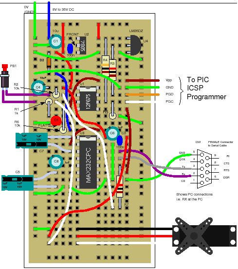
Solderless breadboard
The project uses the same solderless breadboard as before but adds in a link from the serial port connector to the MAX232 transceiver (for receiving serial data) and a 1k resistor.
Circuit diagram
The servo controller only needs a single control line from the 12F675 and a serial input line from the PC serial port to send commands to the circuit.
Again the timing source is provided by the internal 4MHz clock .
ServoController Software operation
Accurate timed pulses are generated using Timer 1 interrupts. For this project Timer 1 is enabled after Timer 0 triggers.When Timer 0 triggers it enables the Timer 1 interrupt and just before this sets the Timer 1 overflow so that the Timer 1 interrupt will occur at an exact time from the triggering of Timer 0.
Also when Timer 0 triggers the servo pin is set high and when Timer 1 triggers the servo pin is set low. In this way an exact output pulse is generated to control the servo motor.
Note: This project does nothing until you type in commands – it does continuously generate the servo position signal but this is only changed from the zero position when a new command is accepted.
Servo Controller : Timer 0
The settings for Timer 0 are exactly the same as those used in Tutorial 6.
Servo Controller : Multitasking
The most interesting part of the servo controller software is that it is doing two things at once – it uses a simple multitasking method that is suitable for use in a memory constrained device e.g. 12F675.
The software services two processes at once:
- Serial port input monitoring.
- Servo motor output.
For more general information on multitasking click here.
As this is not a true multitasking system in which portions of time are allocated to each process you need to carefully decide what the highest priority tasks and lowest priority tasks are before coding starts.
About The Author
Ibrar Ayyub
I am an experienced technical writer holding a Master's degree in computer science from BZU Multan, Pakistan University. With a background spanning various industries, particularly in home automation and engineering, I have honed my skills in crafting clear and concise content. Proficient in leveraging infographics and diagrams, I strive to simplify complex concepts for readers. My strength lies in thorough research and presenting information in a structured and logical format.
Follow Us:LinkedinTwitter