Crime in general is still on the rise, and having a security alarm installed is no longer a perquisite of the wealthy! Here is a simple and compact security alarm system to protect your home/shop and valuables. The circuit is built around a tiny microcontroller chip PIC12F675. Besides, a ready-made Passive Infrared (PIR) module is integrated with the alarm system for reliable human-motion detection.
The built-in passive infrared sensor detects human movement by sensing temperature changes over the scene, and works even in the total darkness.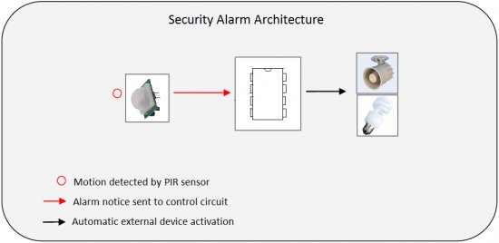 Human body heat moving across the scene will trigger the PIR sensor, and the trigger signal will be sent to the control circuit instantly. As the output of the alarm system can be connected to external lamps or alarm sirens, these devices will be instantly activated upon the detected motion. As a result, the intruder who entered the guarded area, even in total darkness, will instantly be exposed.
Note that PIR sensor can be used not only for detecting motion in the darkness, but it can even be used effectively in daytime where it may produce much less false alarms compared to other motion detection mechanisms. Here, the PIC12F675 works as a “logic interface” between the detection device and the alarm actuator.
Security Alarm Circuit Description
As stated, this project describes a home security alarm based on a Passive Infra-Red sensor module (PIR1). There are many vendors that manufacture the PIR sensor modules and almost all of them are pretty much the same in function. They have a single output that goes high (3.3V) when the motion is detected. Hera, a PIC12F675 (IC1) microcontroller continuously monitors the output from the PIR sensor module and turns an electro-magnetic relay (RL1) on when it goes active.
The circuit can be powered from four AA/AAA cells that gives 6 VDC supply. A 1N4007 (D1) diode is used in series to drop the voltage down to near 5.3 V as the operating voltage for the PIC microcontroller should be below 5.5 V. As well, this diode provides the protection to the whole electronics in case of reverse polarity of the power supply. PIR sensor modules usually have a 3-pin connection (Vcc, Output, and round). The pinout may vary, so it is recommend to check the manufacturer’s datasheet to confirm the pins. Sometime, they do have labels on the PCB next to the pins. Most PIR sensor modules can be powered through 5 to 12 VDC supply as it has its own “low-drop voltage regulator” chip, on board.
The output of the PIR sensor module (PIR1) is monitored through GP5 (pin 2) of PIC12F675. PIC12F675 is an 8-Pin Flash-Based 8-Bit CMOS Microcontroller. Note that,here the PIC12F675 microcontroller uses the internal clock oscillator at 4.0 MHz. When the motion is sensed, this output is high at about 3.3 V . You could still use this voltage as a valid logic high for IC1 by changing the code , but It is preferred to use this voltage to drive the base of a BC547 transistor (T1) so that at the collector we will have the full swing of the logic voltages.
When power supply is turned on by the on/off switch (S1), IC1 monitors the voltage at the collector of the transistor after a delay of about 60 seconds. This initial delay is introduced deliberately to avoid false triggerings, because the PIR sensor requires an initial stabilization time of about 10 to 60 seconds in order to function properly. A red LED (LED1) is connected to port GP0 of IC1 (pin7) with a current limiting resistor (R3) in series. The LED blinks at a slow rate during this delay time.
After this delay, IC1 starts monitoring the voltage at the collector of T1. The LED blinking pattern is now changed to indicate the “standby” mode. In standby mode, T1 is cut off, and the collector output is at logic high (+5 V). When a “valid” motion is sensed, the high output from the PIR sensor module saturates the transistor and the voltage at the collector drops down to logic low. Consequently, of port GP1 (pin 6) of IC1 goes high to switch on the 5V DPDT relay (RL1) through transistor T2. This output will remain High, as long as the motion exists, and this active condition is indicated by a steady-glow of LED1. DPDT Switching contacts of RL1 can be connected to powerful external lamps and/or alarms.
For more detail: PIC12F675 Microcontroller Based Security Alarm Circuit
About The Author
Ibrar Ayyub
I am an experienced technical writer holding a Master's degree in computer science from BZU Multan, Pakistan University. With a background spanning various industries, particularly in home automation and engineering, I have honed my skills in crafting clear and concise content. Proficient in leveraging infographics and diagrams, I strive to simplify complex concepts for readers. My strength lies in thorough research and presenting information in a structured and logical format.
Follow Us:LinkedinTwitter